

Exposure method and system
a technology of exposure method and system, which is applied in the direction of microlithography exposure apparatus, printers, instruments, etc., can solve the problems of difficult to fill space, difficult to maintain a high purity of purge gas, complicated mechanism, etc., and achieve high function, high throughput, and efficient production
- Summary
- Abstract
- Description
- Claims
- Application Information
AI Technical Summary
Benefits of technology
Problems solved by technology
Method used
Image

Examples
first embodiment
[0024]A preferred first embodiment of the present invention will be explained below with reference to FIGS. 1 to 3. In this embodiment, the present invention is applied to a projection exposure apparatus based on the step-and-scan system to use a vacuum ultraviolet light beam as the exposure light beam.
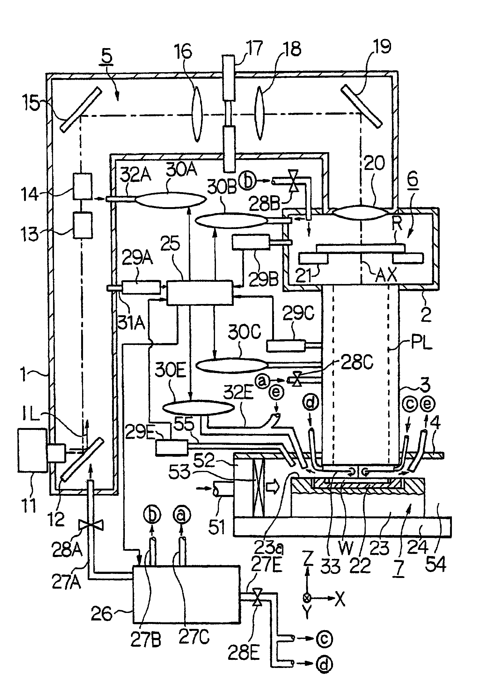
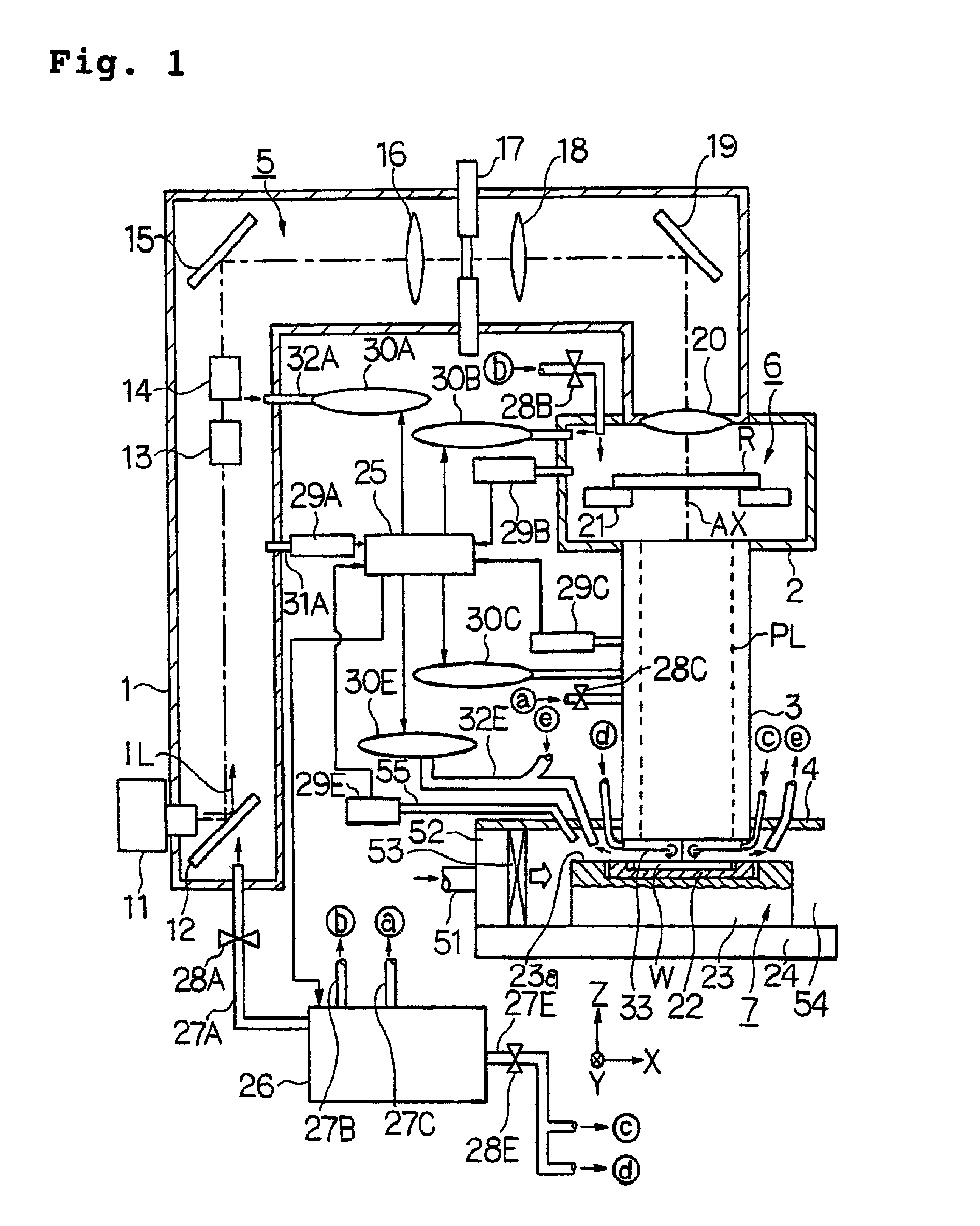
[0025]FIG. 1 shows, with partial cutout, a schematic arrangement illustrating the projection exposure apparatus of this embodiment. With reference to FIG. 1, the mechanical section of the projection exposure apparatus of this embodiment is roughly classified into an illumination optical system unit 5, a reticle-operating unit 6, a projection optical system PL, and a wafer-operating unit 7. Further, the illumination optical system unit 5, the reticle-operating unit 6, and the projection optical system PL are accommodated in an illumination system chamber 1, a reticle chamber 2, and a lens barrel 3 each having a box-shaped configuration in a state in which the illumination optical syste...
second embodiment
[0064]Next, the present invention will be explained with reference to FIG. 4. In FIG. 4, components or parts corresponding to those shown in FIGS. 1 and 2 are designated by the same reference numerals, detailed explanation of which will be omitted.
[0065]FIG. 4 shows a sectional view illustrating an arrangement of those ranging from a projection optical system PL1 to a wafer stage 23 of a projection exposure apparatus of this embodiment. In FIG. 4, an F2 laser beam as a vacuum ultraviolet light beam is used for the exposure light beam IL. The projection optical system PL1 of this embodiment, which is composed of a cata-dioptric optical system, also comprises a first image-forming optical system K1 for forming an intermediate image (primary image) of the pattern on the reticle R, and a second image-forming optical system K2 of the cata-dioptric type for forming a final image of the reticle pattern with a reduction magnification on the wafer W as the photosensitive substrate on the bas...
third embodiment
[0078]Next, the present invention will be explained with reference to FIGS. 6 to 8. In FIGS. 6 to 8, components or parts corresponding to those shown in FIGS. 1 and 2 are designated by the same reference numerals, detailed explanation of which will be omitted.
[0079]FIG. 6 shows a sectional view illustrating an arrangement of those ranging from a projection optical system PL to a wafer stage 23 of a projection exposure apparatus of this embodiment. With reference to FIG. 6, a measuring laser beam LBx is radiated from a laser interferometer 44 onto a reflection surface (alternatively a movement mirror) of a side surface in the +X direction of a wafer stage 23. The laser beam LBx is actually composed of laser beams based on a plurality of axes, for example, of three or more axes. The laser interferometer 44 measures the X coordinate, the angle of rotation about the Y axis (rolling amount), and the angle of rotation about the Z axis (yawing amount) of the wafer stage 23 by receiving an ...
PUM
| Property | Measurement | Unit |
|---|---|---|
| wavelength | aaaaa | aaaaa |
| wavelength | aaaaa | aaaaa |
| wavelength | aaaaa | aaaaa |
Abstract
Description
Claims
Application Information