Magnetoresistive head with spin valve film magnetic sensor element

a magnetic sensor element and magnetoresistive head technology, applied in the field of magnetoresistive head, can solve the problems of short wavelength recording/reproducing characteristics of the gmr head degradation, protection film wear during reading operations, inappropriate formation of protective film, etc., to achieve high mr ratio, good corrosion resistance, and high corrosion resistance

Inactive Publication Date: 2005-11-29
SONY CORP
View PDF3 Cites 20 Cited by
  • Summary
  • Abstract
  • Description
  • Claims
  • Application Information

AI Technical Summary

Benefits of technology

[0036]According to a magnetic head of an embodiment, of the present invention, even when used in tape streamers, the spin-valve film and each of the layers constituting the spin-valve film exhibit high corrosion resistance. Therefore, even under harsh conditions, a high MR ratio can be maintained.
[0037]According to a magnetoresistive head of an embodiment of the present invention, by specifying the corrosion potential of the spin-valve film relative to a standard hydrogen electrode so as to ensure good corrosion resistance and make it possible to maintain a high MR ratio, occurrences of corrosion even under harsh conditions, such as high temperature and humidity conditions, seawater atmosphere or the like, can be prevented, and it becomes possible to perform appropriate reading operations on a magnetic recording medium even in cases where a protective film is not formed on the surface of the magnetoresistive head that contacts the magnetic recording medium.
[0038]In addition, according to an embodiment of a magnetoresistive head of the present invention, by appropriately selecting the material and composition of each layer constituting the spin-valve film, occurrences of corrosion may be prevented, and good corrosion resistance may be obtained.
[0039]In addition, according to an embodiment of a magnetoresistive head of the present invention, by appropriately selecting the material composition of the pinned layer and the free layer of the spin-valve film, a reduction in noise may be achieved.

Problems solved by technology

However, in tape streamers, for which the use of GMR heads is being considered currently, because reading operations are performed under conditions in which the GMR head and the magnetic tape are in contact, if a protective film for preventing corrosion, as mentioned above, is formed on the surface of the GMR head that is placed in sliding contact with the magnetic tape, the protective film wears during reading operations due to the contact between the small protrusions and protective film formed on the surface of the magnetic tape.
Further, because the protective film formed on the surface of the GMR head that contacts the medium creates a space between the magnetic tape, it causes degradation in the short wavelength recording / reproducing characteristics of the GMR head.
Therefore, in magnetic tape apparatuses such as tape streamers, it can be considered inappropriate to form a protective film on the surface of the GMR head that contacts the recording medium.
For this reason, in magnetic tape apparatuses, the surface of the GMR head that contacts the recording medium is in direct contact with the atmosphere, and there was a problem in that when used under harsh conditions such as high temperature and humidity conditions, seawater atmosphere or the like, corrosion was more likely to occur.

Method used


Image

  • Magnetoresistive head with spin valve film magnetic sensor element
  • Magnetoresistive head with spin valve film magnetic sensor element
  • Magnetoresistive head with spin valve film magnetic sensor element

Examples


Embodiment Construction

[0063]Hereinafter, embodiments of magnetoresistive heads according to the present invention will be described in detail with reference to the drawings.

[0064]An example of a magnetic tape apparatus to which an embodiment of a magnetoresistive head of the present invention is applied will be described.

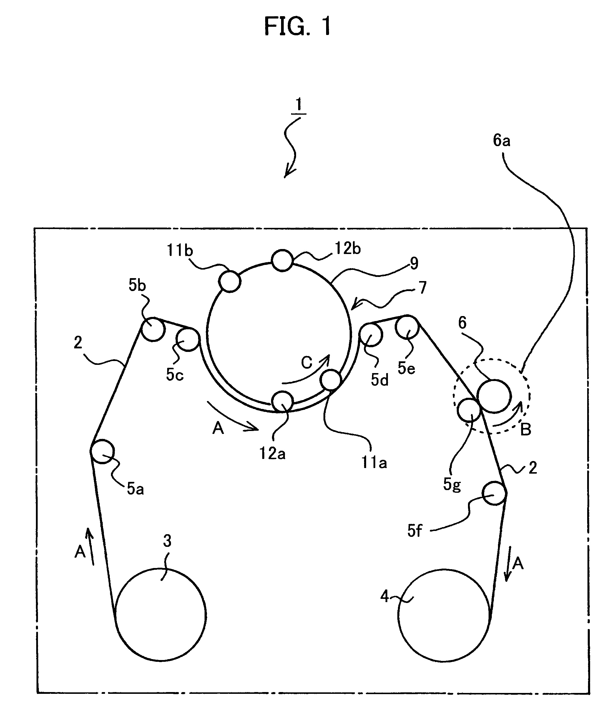
[0065]A magnetic tape apparatus 1 shown in FIG. 1 records and / or reads signals to and from a magnetic tape 2 by the helical scan method.

[0066]The magnetic tape apparatus 1 is provided with a tape supply reel 3 for supplying the magnetic tape 2, a take-up reel 4 for winding the magnetic tape supplied from the supply reel 3, and a plurality of guide rollers 5a to 5f for guiding the magnetic tape 2 between the supply reel 3 and the take-up reel 4. The magnetic tape 2 runs in the direction indicated by arrows A in FIG. 1.

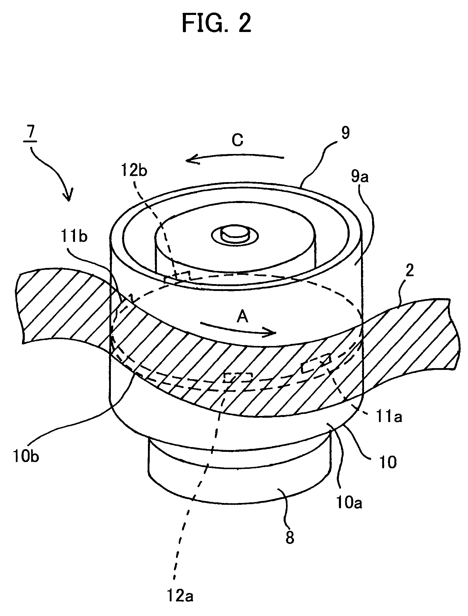
[0067]Further, between guide rollers 5e and 5f, there are provided, as tape running means, a pinch roller 5g that contacts the magnetic tape 2, a capstan 6 which pinches the...


PUM

PropertyMeasurementUnit
corrosion potentialaaaaaaaaaa
current densityaaaaaaaaaa
temperatureaaaaaaaaaa

Abstract

An improvement in the corrosion resistance of a magnetoresistive head is aimed for, and a high magnetoresistivity ratio is maintained. In a magnetoresistive head equipped with, as a magnetic sensor element for detecting magnetic signals while in contact with a magnetic recording medium, a spin-valve film, which has a structure where an anti-ferromagnetic layer, a pinned layer in which the direction of magnetization is pinned in a predetermined direction by an exchange-coupling magnetic field at work between itself and the anti-ferromagnetic layer, a free layer in which the direction of magnetization changes in accordance with an external magnetic field, and a non-magnetic layer for magnetically isolating the pinned layer and the free layer are layered, the corrosion potential of the spin-valve film relative to a standard hydrogen electrode measured while immersed in a NaCl solution of a concentration of 0.1 mol/L is specified at +0.4 [V vs. SHE] or above.

Description

CROSS REFERENCE TO RELATED APPLICATIONS[0001]This application claims priority to Japanese Patent Application Numbers: JP2002-223987 filed Jul. 31, 2002; JP2002-349907 filed Dec. 2, 2002; JP2002-370519 filed Dec. 20, 2002; JP2002-370520 filed Dec. 20, 2002 and JP2003-107774 filed Apr. 11, 2003 respectively which are incorporated herein by reference.BACKGROUND OF THE INVENTION[0002]1. Field of the Invention[0003]The present invention relates to a magnetoresistive head that uses a spin-valve film as a magnetic sensor element for detecting magnetic signals while in contact with a magnetic recording medium.[0004]2. Description of the Related Art[0005]Magnetoresistive elements (hereinafter referred to as MR elements) utilize magnetoresistive effects where the resistance changes depending on the magnitude and direction of an external magnetic field, and are used in, for example, magnetic heads and the like as magnetic sensor elements for detecting the magnetic field of a signal from a magn...

Claims


Application Information

Patent Timeline
Patent Type & Authority Patents(United States)
IPC IPC(8): G11B5/008G11B5/255G11B5/31G11B5/39G11B5/40G11B5/48G11B5/53H01F10/16H01F10/30H01F10/32H01L43/08H01L43/10
CPCB82Y10/00G11B5/3106G11B5/3903G11B5/53G11B5/0086G11B5/255G11B5/40G11B5/4893
Inventor TETSUKAWA, HIROKISODA, YUTAKAOKABE, AKIHIKO
Owner SONY CORP
Why Eureka
Try Eureka