Two-way CATV system

a catv system and two-way technology, applied in the field of two-way catv systems, can solve the problems of thermal noise generated by amplifiers and terminals in subscriber homes, insufficient management of transmission quality at a high quality level with stability, and jump-in noise, so as to eliminate non-linear circuit noise and high quality

Inactive Publication Date: 2006-01-24
GOOGLE LLC
View PDF24 Cites 7 Cited by
  • Summary
  • Abstract
  • Description
  • Claims
  • Application Information

AI Technical Summary

Benefits of technology

[0024]According to a thirteenth aspect of the present invention, in the two-way CATV system according to the first or second aspect of the invention, the bias voltage superposing element may include a transformer for boosting the AC bias voltage with which the downstream signal is superposed, a switch element for applying a large voltage in burst on a time-period basis for a short time, and a filter element for filtering only the burst bias current.
[0025]According to a fourteenth aspect of the present invention, in the two-way CATV system according to the first or second aspect of the invention, the bias voltage superposing element may include an element for boosti

Problems solved by technology

In the two-way CATV system introduced so far, however, with respect to upstream signals (a transmission band is, e.g., 10 MHz to 55 MHz), the usage thereof is limited to a data transmission of monitor signals of home terminals of subscriber homes, amplifiers on the CATV transmission path and power supply devices to the amplifiers, and to temporary utilization for relay transmission to a CATV center station from an event site, and hence a transmission quality thereof is not necessarily sufficiently managed at a high quality level with stability.
The first cause is the thermal noises generated from the amplifiers and the terminals in the subscriber homes.
Further, the second cause may be jump-in noises from outside, viz., the external noises derived from amateur radio operations and citizen's band operations.
Fur

Method used


Image

  • Two-way CATV system
  • Two-way CATV system
  • Two-way CATV system

Examples


Embodiment Construction

[0044]Embodiments of the present invention will hereinafter be described with reference to the accompanying drawings.

[0045][Whole Structure of Two-Way CATV System]

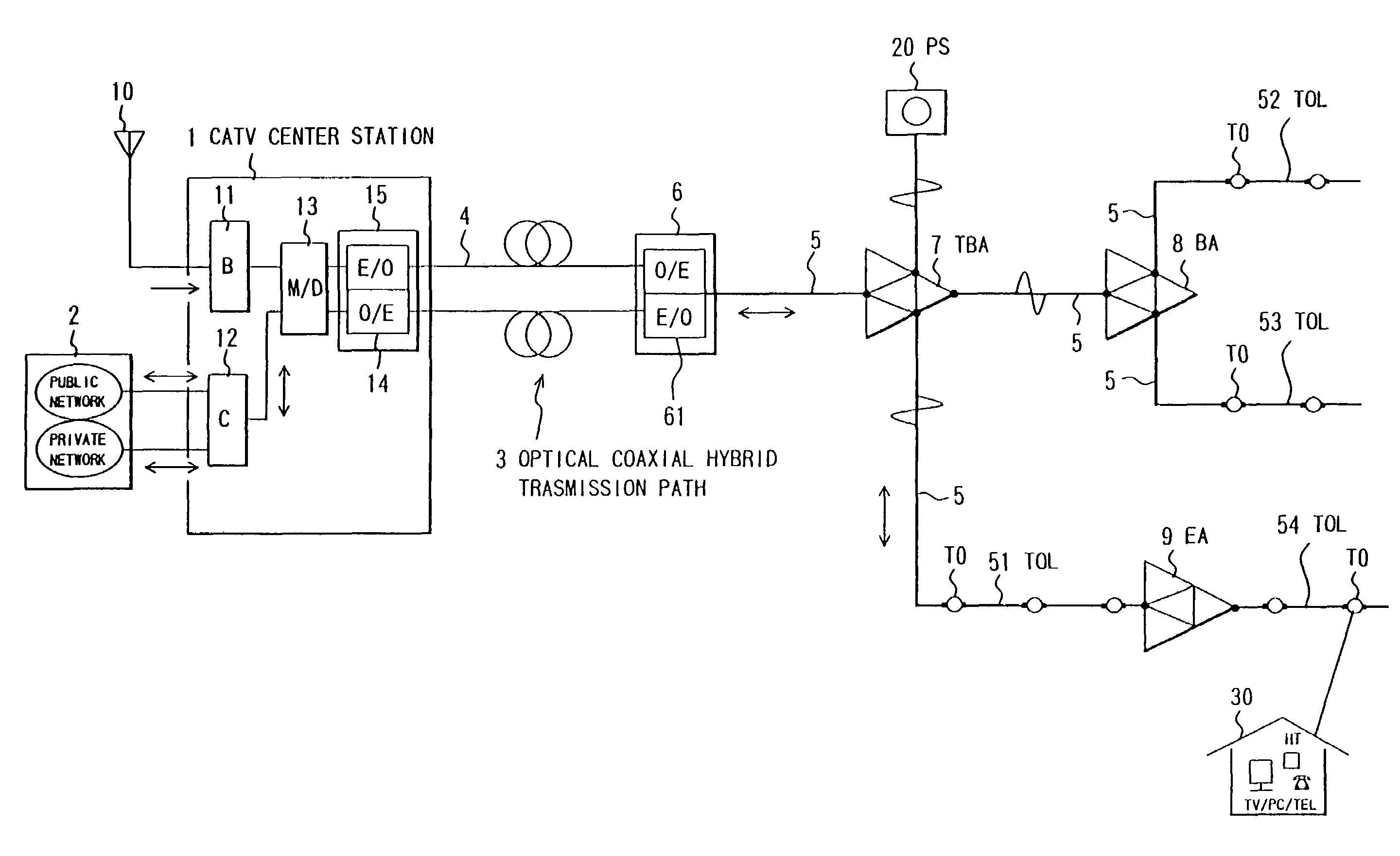
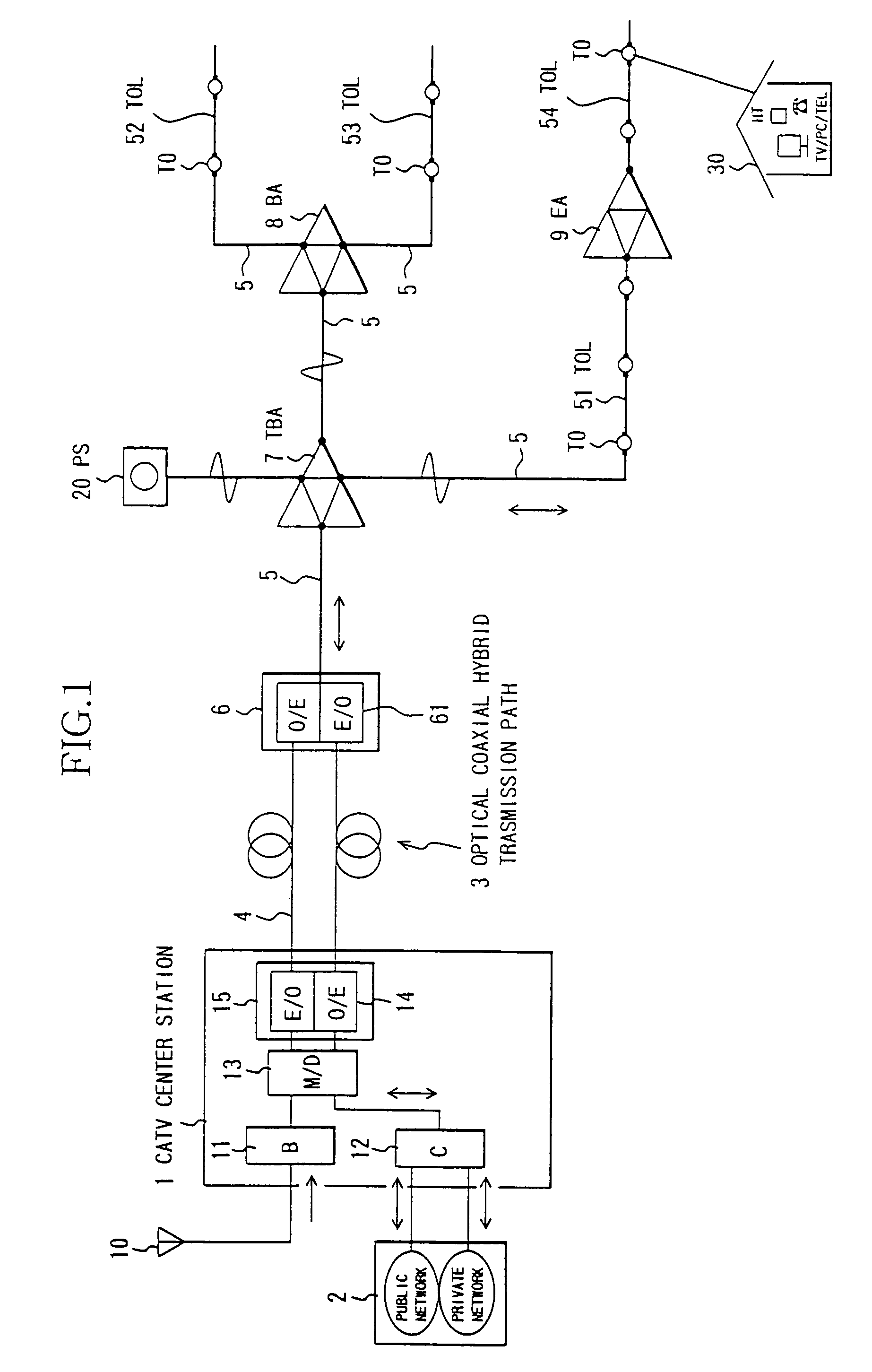
[0046]FIG. 1 shows a structure of a two-way CATV system in one embodiment of the present invention. Referring to FIG. 1, a CATV center station (head end) 1 is constructed of a broadcasting device (B)11 for frequency conversion, processing, and retransmitting RF signals derived from TV broadcasting received via an antenna 10, and local origination broadcasting, etc., a two-way communications device (C)12 including a router and a switch for transmitting and receiving communications information (speech and data) to and from other networks 2 such as a public network, an appropriate network and the Internet, a multiplexer / demultiplexer (M / D) 13, and a optical transmitter / receiver (T / R) 15 including an electro-optic / opto-electric (E / O, O / E) converter 14.

[0047]The multiplexer 13 transmits, to the optical transmitter, the RF signa...


PUM


Abstract

A two-way CATV system is easy of maintenance, stable of a transmission quality and capable of restraining inter-modulation distortion noises of downstream RF signal carriers which are caused by non-linearity of electric contact members of coaxial connectors among upstream ingress noises becoming a problem when performing communications services by utilizing a CATV transmission path. The two-way CATV system comprises at least one bidirectional amplifier provided on a CATV transmission path for connecting a CATV center station to a subscriber home, a bias voltage superposing element for superposing, with a bias voltage, a downstream signal transmitted along a coaxial transmission path subordinate to an amplifier at the terminal among the bidirectional amplifiers, and a bias current adjusting load element, provided at the end of the coaxial transmission path, for setting the bias current corresponding to an application of the bias voltage superposed by the bias voltage superposing element.

Description

BACKGROUND OF THE INVENTION[0001]The present invention relates generally to a two-way CATV system and, more particularly, to a two-way CATV system capable of restraining upstream ingress noises which might become a problem in the case of performing communication services by utilizing a CATV oriented transmission path (CATV line), and of facilitating the maintenance.[0002]A CATV (Community Antenna Television) system is constructed for the purpose of retransmitting broadcast programs in TV broadcasting, satellite broadcasting, local origination broadcasting, etc., wherein information signals are transmitted only in a downstream direction to individual subscriber homes, etc. from a CATV center station (head end).[0003]Over the recent years, a two-way CATV system has been introduced, wherein not only a broadcasting device but also a two-way communication device are installed within a CATV center station of the CATV system, the CATV transmission being structured as an optical coaxial hyb...

Claims


Application Information

Patent Timeline
IPC IPC(8): H04N7/173H04B3/02H04B15/00H04H20/76H04H20/78H04H20/79H04N5/00H04N7/10H04N7/16H04N21/647
CPCH04H20/76H04H20/79H04N21/812H04N21/4722H04N7/102
Inventor SATO, HIROAKISUDO, YOZO
Owner GOOGLE LLC
Why Eureka
Try Eureka