
Single and multiband quarter wave resonator

Inactive Publication Date: 2006-01-31
TYCO ELECTRONICS LOGISTICS AG (CH)
View PDF4 Cites 54 Cited by
  • Summary
  • Abstract
  • Description
  • Claims
  • Application Information

AI Technical Summary

Benefits of technology

[0013]It is another object of the invention to provide an antenna unit which is lightweight, compact, highly reliable, and efficiently produced.
[0014]The present invention replaces the external wire antenna of a wireless communication device with a printed dielectric substrate element which is disposed within the housing of a wireless device and closely-spaced to the printed wiring board (PWB) and antenna feedpoint of the wireless device. Electrical connection to the wireless device's PWB may be achieved through automated production equipment, resulting in cost effective assembly and production. Electrical performance of the internal (embedded) antenna in wireless systems is nominally equal to that of a conventional wire antenna.
[0015]It is an object of the present invention to provide an antenna assembly which can resolve the above shortcomings of conventional antennas. Additional objects of the present invention include: the elimination of the external antenna and its attendant faults such as susceptibility to breakage and impact on overall length of the transceiver; the provision of an internal antenna that can easily fit inside the housing of a wireless transceiver such as a cell phone, with minimal impact on its length and volume; the provision of a cost effective antenna for a wireless transceiver, having electrical performance comparable to existing antenna types; and, the reduction in SAR (specific absorption rate) of the antenna assembly, as the antenna exhibits reduced transmit field strength in the direction of the user's ear for hand held transceivers such as a cellular telephone, when compared to the field strength associated with an external wire type antenna system.
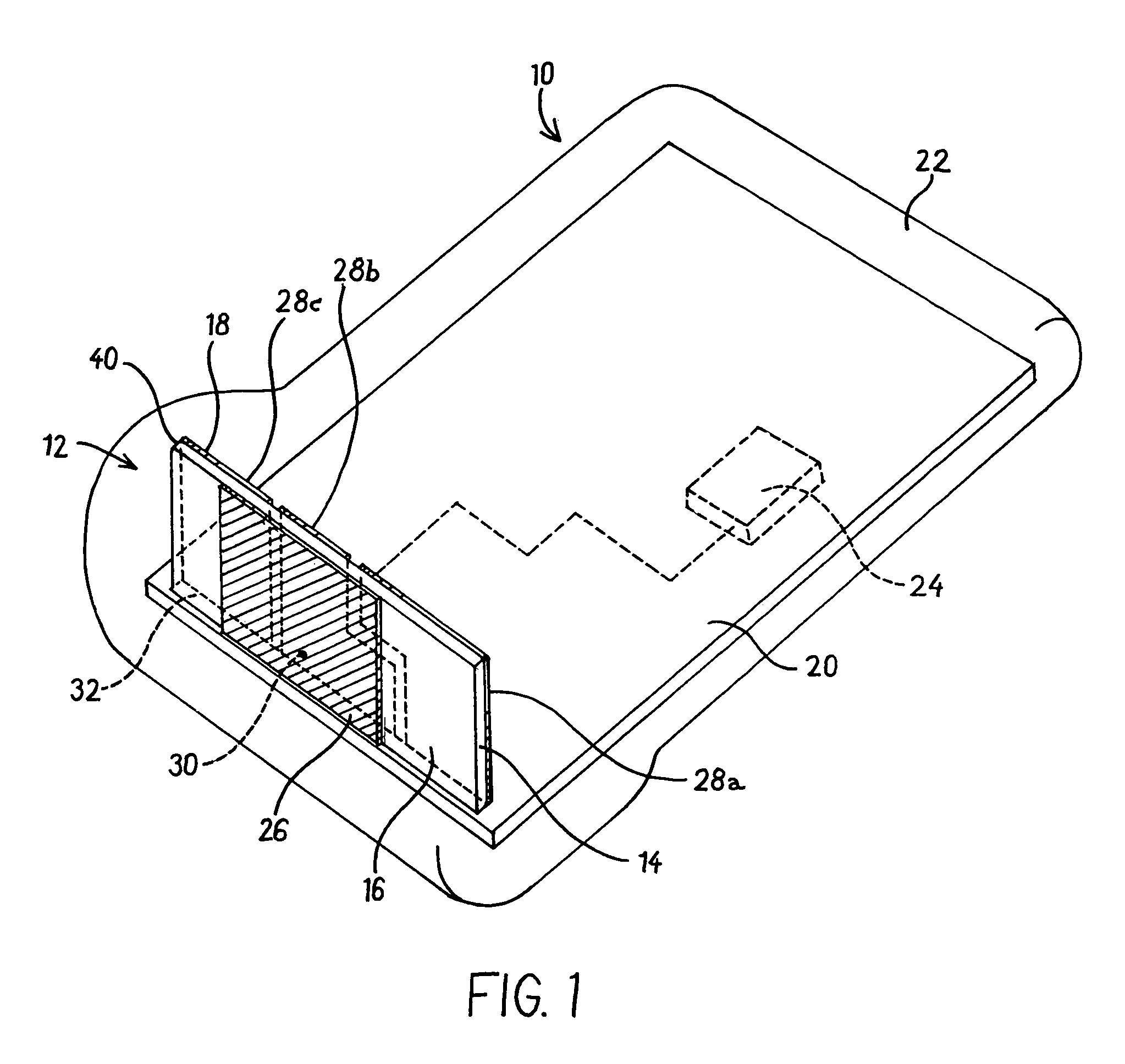
[0017]It is an object of the present invention to provide a GPS (Global Positioning System) antenna quarter wave resonator and single or multiband antenna quarter waves resonator for wireless communications frequencies that are co-located on a common second conductor to form an asymmetrical dipole dual or multiband antenna system with separate feed for the GPS antenna portion. The common second conductor may be supplied by the PWB of a wireless communication device such as a cell phone. The GPS and wireless band resonators may be formed as printed circuits on a dielectric substrate using known circuit board fabrication processes and techniques, resulting in a low cost antenna suitable for high volume manufacturing.
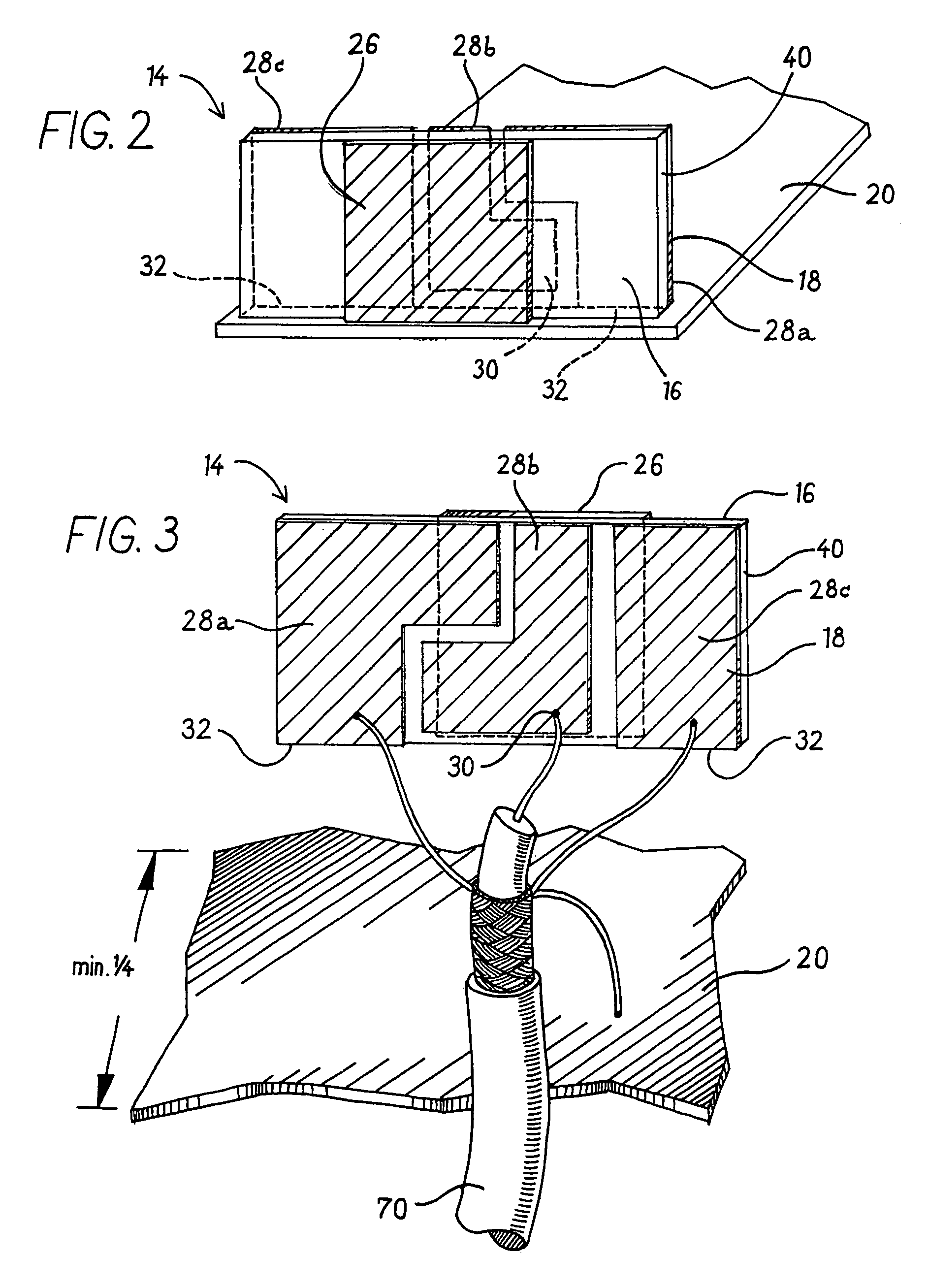
[0018]The present invention provides an antenna assembly including a first conductive trace element disposed upon the resonator element. The resonant frequency range of the trace may be selected to exhibit ¼ wave resonance. In the preferred embodiment the first printed circuit element is rectangular having a thickness in the range 0.010–0.125 inches. Alternatively, the conductive trace may be printed on any number of conventional dielectric materials having a low to moderate dielectric loss such as plastics and fiberglass. Furthermore, the compact size of the resonator element may conform to available volume in the housing of a wireless transceiver such as a cellular telephone. The antenna assembly may be excited or fed with 50 ohm impedance, which is a known convenient impedance level found at the receiver input / transmitter output of a typical wireless transceiver.

Problems solved by technology

Such antennas are inconvenient and susceptible to damage or breakage.
The microstrip patch may be installed internally in some wireless communications devices, and size for 1575 MHz is typically reduced by dielectric loading, which also increases costs and weight.
The quadrifilar helix is of substantial size, and is mounted externally, where it is subject to damage.

Method used


Image

  • Single and multiband quarter wave resonator
  • Single and multiband quarter wave resonator
  • Single and multiband quarter wave resonator

Examples


second embodiment

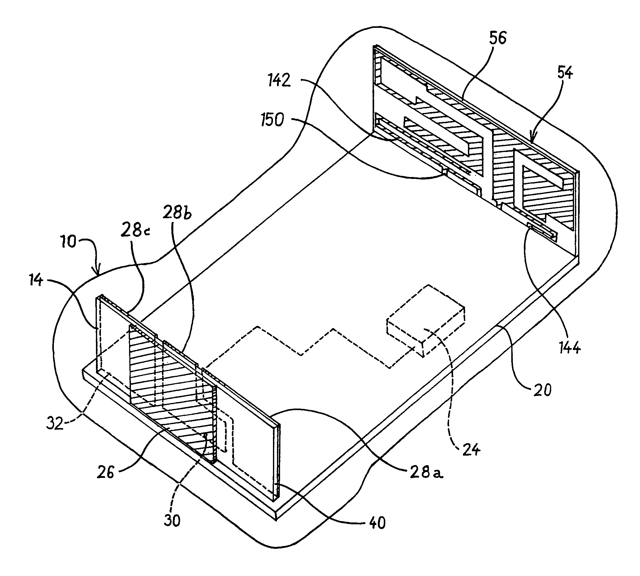
[0034]Referring now to FIG. 4, the present invention is disclosed to include a second antenna 54 having a dielectric substrate 56 and disposed within a wireless communications device at an end opposite to the first resonator element 14. The antenna assembly 54 is likewise incorporated within the handset of a communications device 10. The second printed antenna 54 may include a single- or multiple-band wave resonator disposed relative to the ground plane 20 at an angle of 0–90 degrees. The ground plane 20 is preferably the ground traces of the PWB of a wireless communications device 10. Referring particularly to FIG. 5, the second resonator element 54 may include a multiple-band resonator as disclosed in the assignees's U.S. patent application Ser. No. 09 / 382,179, herein incorporated by reference in its entirety. FIG. 5 depicts a tri-band antenna assembly 54 functioning across a cellular band (880–960 MHz.), a PCS band (1710–1880 MHz.) and the BLUETOOTH™ band (2.4–2.5 GHz). Cellular ...

third embodiment

[0035]FIG. 6 illustrates a perspective view of a GPS and wireless frequency band antenna 14, 54. A GPS quarter wave resonator 14 is fed by microstrip transmission line 60 disposed upon a dielectric substrate element 62 opposite a ground plane 64. A single or multiband quarter wave resonator 54 for a wireless communications band or bands may be utilized on dielectric substrate 56. The dielectric substrates 40, 56, 62 may be mechanically connected for structural integrity.


PUM


Abstract

A single or multiple band quarter wave resonator antenna assembly for a communications device including a resonator element as a substrate element having disposed thereupon at least a pair of conductor trace elements. The conductor trace elements are disposed upon opposite sides of the substrate element and are operatively coupled to the communications device. The antenna assembly further including a separate conductive member having an approximate ¼ wavelength or greater dimension, which may be defined as the internal printed wiring board ground plane of the communications device.

Description

[0001]This application claims the benefit of priority pursuant to 35 USC §119(e)(1) from the provisional patent application filed pursuant to 35 USC §111(b): as Ser. No. 60 / 157,945 on Oct. 6, 2000.[0002]This is a continuation-in-part of application Ser. No. 09 / 382,179 filed on Aug. 24, 1999, now U.S. Pat. No. 6,239,765 the benefit of priority from which is hereby claimed pursuant to the provisions of 35 USC §120.FIELD OF THE INVENTION[0003]The present invention relates to an antenna assembly for a wireless communication device, such as a cellular telephone. Particularly, the present invention relates to compact antenna assemblies including a GPS-frequency quarter wave resonator and a single or multiple band quarter wave resonator of associated wireless communication devices.BACKGROUND OF THE INVENTION[0004]Known wireless communications devices such as hand-held cell phones and data modems (LANs) typically are equipped with an external wire antenna (whip), which may be fixed or teles...

Claims


Application Information

Patent Timeline
IPC IPC(8): H01Q1/38H01Q1/24H01Q5/00H01Q5/371H01Q5/378H01Q5/40H01Q9/04H01Q9/28H01Q13/08
CPCH01Q1/243H01Q1/38H01Q9/0421H01Q5/40H01Q13/08H01Q5/371H01Q5/378H01Q9/285
Inventor HONDA, ROYDENJOHNSON, GREGHILL, ROBERTKEILEN, DON
Owner TYCO ELECTRONICS LOGISTICS AG (CH)
Learn More