Method for machining glass substrate

Inactive Publication Date: 2006-03-07
NAT INST OF ADVANCED IND SCI & TECH +1
View PDF11 Cites 44 Cited by
  • Summary
  • Abstract
  • Description
  • Claims
  • Application Information

AI Technical Summary

Benefits of technology

[0014]A V-shaped groove formed in a surface of a glass substrate by a method for machining the glass substrate according to the present invention is provided so that an angle between opposite side surfaces of the V-shaped groove can change in a range of from 30 degrees to 120 degrees. Further, the glass substrate in which th

Problems solved by technology

Because the retention of the optical fiber or the like is performed for the purpose of aligning the optical axis of the optical fiber with that of another optical device, such movement causes a problem.
Further, in the method, the angle of the V-shape is determined crystallographically uniquely, so that the angle cannot be adjusted.
The higher performance is required of the optical device, the more serious problem is characteristic variation owing to the temperature of an optical system.
This problem is caused by the expansion/contraction of each of optical devices constituting an optical system in accordance with the change of the temperature and is caused by the change of the optical path length in accordance with the change of the refractive index.
For example, the thermal expansion coeffi

Method used


Image

  • Method for machining glass substrate
  • Method for machining glass substrate
  • Method for machining glass substrate

Examples


embodiment 1

[Embodiment 1]

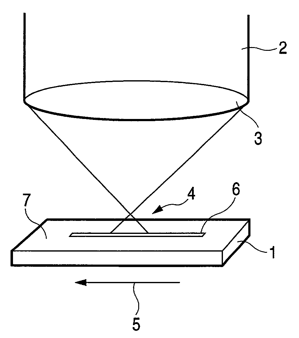
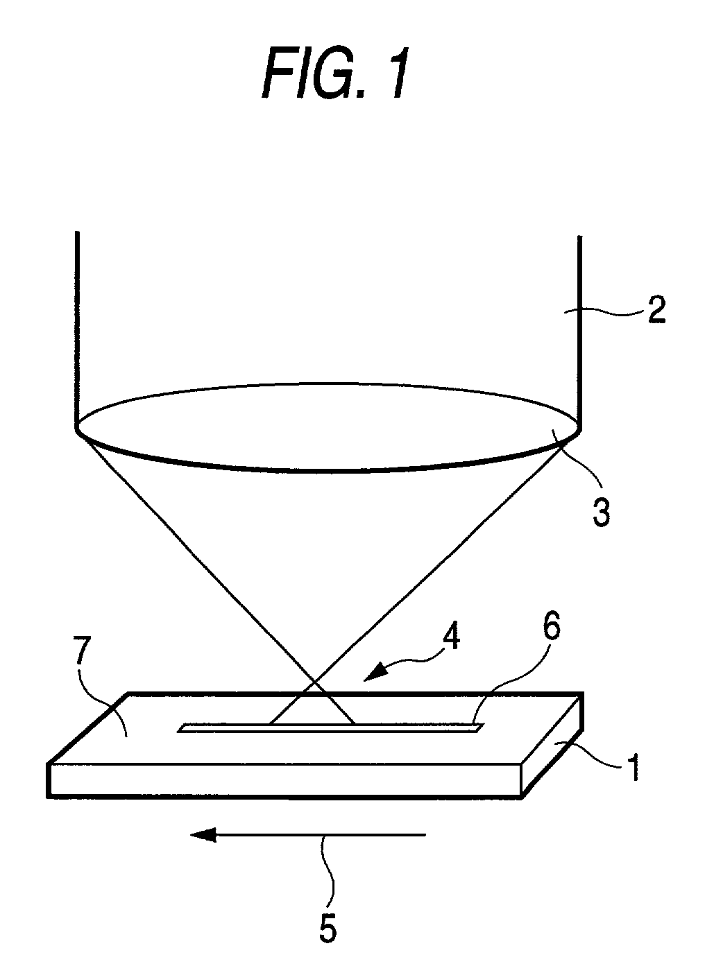
[0029]A plate-like glass substrate having a composition shown in Table 1, having a value of 89.2×10⁻⁷° C.−1 as a mean thermal expansion coefficient at a temperature of 0° C. to 300° C. and having a size of 20 mm×30 mm×2 mm was irradiated with a pulsed laser beam 2 condensed by a lens 3 as shown in FIG. 1. As the pulsed laser beam 2, there was used a laser beam which had a pulse width of 100 femtoseconds, a repetition frequency of 1 kHz, a wavelength of 800 nm and a mean output of 950 mW and which was oscillated by an argon-laser-excited titanium-sapphire (Ti:Al2O3) laser (not shown). After the laser beam was transmitted through an ND filter so as to be adjusted to have 500 mW intensity, the laser beam was condensed by a ten-fold objective lens 3 with a numerical aperture (NA) of 0.3 and the focal position 4 of the laser beam 2 was adjusted so as to be located far by 150 μm outside and above a surface 7 of the substrate 1. A V-shaped groove 6 was formed while the substr...

embodiment 2

[Embodiment 2]

[0031]A V-shaped groove was produced by use of the same substrate material and the same laser beam source as those used in Embodiment 1 except that the focal position of the laser was changed so as to be located far by 125 μm outside and above the surface 7 of the substrate 1.

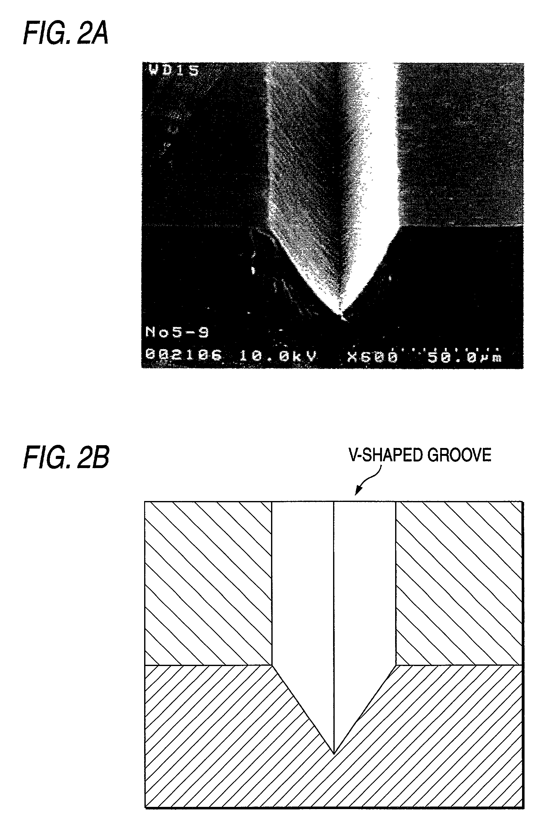
[0032]When the shape of the V-shaped groove formed was confirmed by a scanning electron microscope, the groove width W was 49 μm, the depth d was 67 μm, and the angle θ between the side surfaces 8 of the V-shaped groove was 40 degrees.

embodiment 3

[Embodiment 3]

[0033]A V-shaped groove was produced by use of the same substrate material and the same laser beam source as those used in Embodiment 1 except that the focal position of the laser was changed so as to be located far by 175 μm outside and above the surface 7 of the substrate 1.

[0034]When the shape of the V-shaped groove formed was confirmed by a scanning electron microscope, the groove width W was 53 μm, the depth d was 19 μm, and the angle θ between the side surfaces 8 of the V-shaped groove was 110 degrees.


PUM

PropertyMeasurementUnit
Lengthaaaaaaaaaa
Timeaaaaaaaaaa
Angleaaaaaaaaaa

Abstract

In the present invention, a surface 7 of a glass substrate 1 is irradiated with a laser beam 2 to thereby form a V-shaped groove 6. At that time, the laser beam 2 is condensed outside and above the glass substrate 1. The distance between a beam-condensing point 4 of the laser beam 2 and the surface 7 of the glass substrate 1 is changed to thereby make it possible to change the angle between opposite side surfaces of the V-shaped groove. The angle is in a range of from 30 degrees to 120 degrees. Further, the laser beam used in the present invention is pulsed light, preferably with a pulse width not larger than 10 picoseconds.

Description

BACKGROUND OF THE INVENTION[0001]The present invention relates to a method for machining a glass substrate in which a groove-like concave portion is formed in a surface of the glass substrate, and particularly to a method for forming a V-shaped groove in the surface of the glass substrate by laser ablation.[0002]A groove-like concave portion formed in a substrate is used as a member for retaining an optical device such as an optical fiber, a rod lens or the like, or as an optical device such as a diffraction grating or the like. When the groove formed in the substrate is used as a member for retaining an optical fiber or the like, it is important that a section of the groove perpendicular to a lengthwise direction of the groove is V-shaped. In the case where the groove section is U-shaped or rectangularly shaped, retention of the optical fiber or the like in the groove is performed not with line contact but with surface contact so that the size of the groove section is required to b...

Claims


Application Information

Patent Timeline
IPC IPC(8): C03C15/00B23K26/00B23K26/364C03B33/09C03C23/00
CPCB23K26/0635C03C23/0025B23K26/367Y10T428/24479B23K26/364B23K26/0624
Inventor KAMADA, KENJIOHTA, KOJIYAMAGUCHI, JUNKOYAMA, TADASHI
Owner NAT INST OF ADVANCED IND SCI & TECH
Why Eureka
Try Eureka