Method of manufacturing expansile filamentous embolization devices

a filamentous embolization and filament technology, applied in the field of body cavity occlusion devices, can solve the problems of balloon rupture during inflation, difficult visualization, and difficult to retrieve or move after solidifying fluid sets, and achieve the effects of promoting effective embolization, excellent location control, and reducing the risk of vascular ruptur

Inactive Publication Date: 2006-03-21
MICROVENTION INC
View PDF87 Cites 130 Cited by
  • Summary
  • Abstract
  • Description
  • Claims
  • Application Information

AI Technical Summary

Benefits of technology

[0042]The present invention provides a number of significant advantages. Specifically, the present invention provides an effective body cavity or vascular embolization device that can be deployed within a cavity or vascular site with excellent locational control, and with a lower risk of vascular rupture, tissue damage, or migration than with prior art devices. Furthermore, the embolization device effects a conformal fit within the site that promotes effective embolization, and yet its ability to be delivered t

Problems solved by technology

While the balloon-type embolization device can provide an effective occlusion of many types of aneurysms or other body cavities, it is difficult to retrieve or move after the solidifying fluid sets, and it is difficult to visualize unless it is filled with a contrast material.
Furthermore, there are risks of balloon rupture during inflation and of premature detachment of the balloon from the catheter.
The direct injection of liquid polymer embolic agents has proven difficult in practice.
For example, migration of the polymeric material from the aneurysm and into the adjacent blood vessel has presented a problem.
In addition, visualization of the embolization material requires that a contrasting agent be mixed with it, and selecting embolization materials and contrasting agents that are mutually compatible may result in performance compromises that are less than optimal.
Furthermore, precise control of the deployment of the polymeric embolization material is difficult, leading to the risk of improper placement and/or premature solidification of the material.
Moreover, once the embolization material is deployed and solidified, it is difficult to move or retrieve.
Microcoils have been less successful in the treatment of larger aneurysms, especially those with relatively wide necks.
A disadvantage of microcoils is that they are not easily retrievable; if a coil migrates out of the aneurysm, a second procedure to retrieve it and m

Method used


Image

  • Method of manufacturing expansile filamentous embolization devices
  • Method of manufacturing expansile filamentous embolization devices
  • Method of manufacturing expansile filamentous embolization devices

Examples


second embodiment

[0097]The Embolization Device: Second Preferred Embodiment. FIGS. 14 through 23 illustrate an embolization device in accordance with a second preferred embodiment of the present invention. Referring first to FIGS. 14 through 17, a device 100 in accordance with this second embodiment comprises an elongate, flexible, filamentous carrier 102 on which an expansile embolizing element 104 is non-releasably carried. The carrier 102 is preferably formed from a continuous length of hollow microcoil 106, made from a suitable metal such as platinum, gold, tungsten, or tantalum, or a metallic alloy, such as stainless steel or Nitinol. Of these materials, platinum and Nitinol are preferred. The microcoil is formed with tightly-packed coils, so that there is little or no spacing between adjacent coils. The carrier 102 may also include a filamentous core 108 extending axially through the microcoil 106. The core 108 is a thin metal wire, preferably made of a shape memory metal such as Nitinol. The ...

third embodiment

[0116]The Embolization Device: Third Exemplary Embodiment and First Method for Making It: A third exemplary embodiment of a device 300 for occluding a body cavity is illustrated in FIGS. 32–35, and a first exemplary embodiment of a method for making the device 300 is illustrated in FIGS. 24–31.

[0117]As shown in FIG. 32, the embolization device 300 comprises an elongated, filamentous carrier 302, and an embolizing element comprising a coaxial member 304 of an expansile, hydrophilic polymer, or hydrogel, described in detail above, encapsulating at least a portion of the length of the carrier.

[0118]Although the coaxial polymer embolizing member 304 is shown in the figures as having a substantially cylindrical shape, it should be understood that the member, and indeed, the carrier encapsulated within it, can have a wide variety of other cross-sectional shapes, e.g., polygonal, longitudinally grooved, and the like, depending on the particular application at hand.

[0119]The carrier 302 may...

fourth embodiment

[0127]The Embolization Device: Fourth Exemplary Embodiment and Second Method for Making It: A fourth exemplary embodiment of an embolization device 400 for occluding a body cavity is illustrated in FIGS. 39–42, and a second exemplary embodiment of a method for making the device 400 is illustrated in FIGS. 36–38.

[0128]As illustrated in FIGS. 39 and 41, respectively, two possible variants of the fourth exemplary embodiment of embolization device 400 both comprise, as in the case of the third exemplary embodiment 300 described above, an elongated, filamentous carrier 402, and a coaxial member 404 of an expansile, hydrophilic polymer, or hydrogel, encapsulating at least a portion of the length of the carrier. Further, in both variants, the carrier 402 may, like the third embodiment above, comprise either an elongated strand of a flexible, biocompatible material, e.g., platinum wire, or a flexible tube.

[0129]However, in contrast to the third embodiment of the device 300 above, in the fir...


PUM

PropertyMeasurementUnit
Lengthaaaaaaaaaa
Lengthaaaaaaaaaa
Distanceaaaaaaaaaa

Abstract

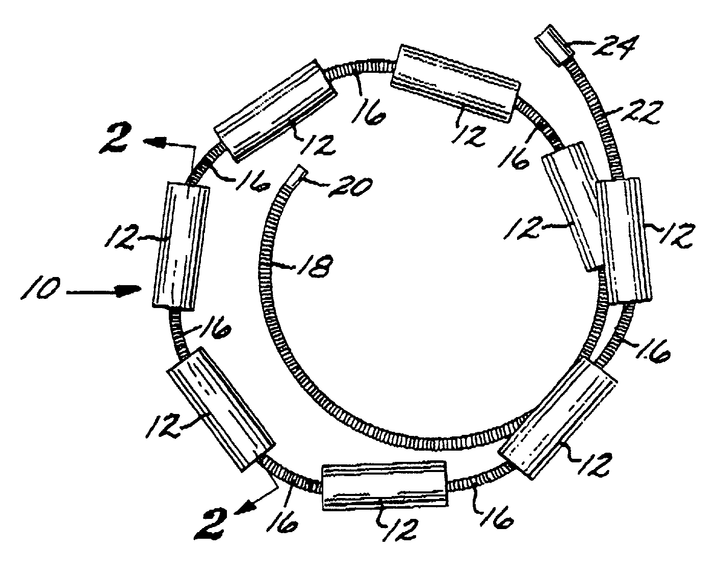
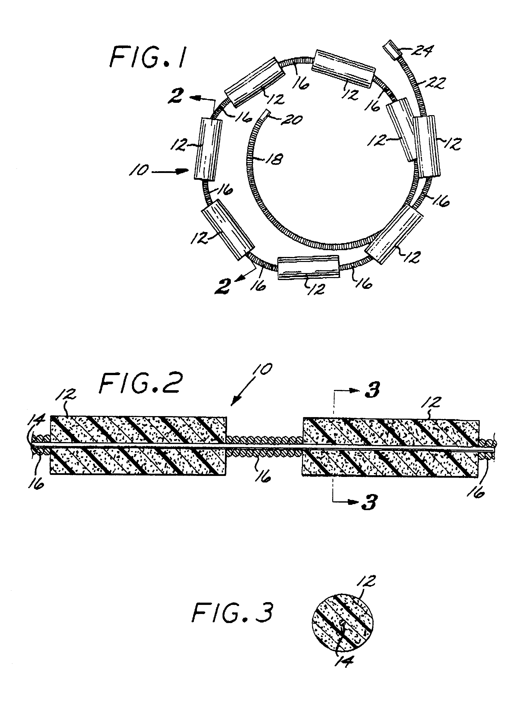
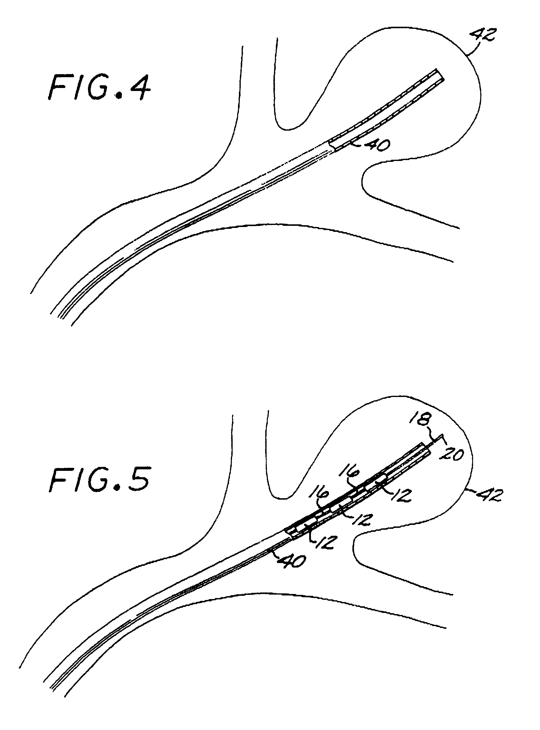
An embolization device for occluding a body cavity includes one or more elongated, expansible, hydrophilic embolizing elements non-releasably carried along the length of an elongated filamentous carrier that is preferably made of a very thin, highly flexible filament or microcoil of nickel/titanium alloy. At least one expansile embolizing element is non-releasably attached to the carrier. A first embodiment includes a plurality of embolizing elements fixed to the carrier at spaced-apart intervals along its length. In second, third and fourth embodiments, an elongate, continuous, coaxial embolizing element is non-releasably fixed to the exterior surface of the carrier, extending along a substantial portion of the length of the carrier proximally from a distal tip, and optionally includes a lumenal reservoir for delivery of therapeutic agents. Exemplary methods for making these devices include skewering and molding the embolizing elements. In any of the embodiments, the embolizing elements may be made of a hydrophilic, macro-porous, polymeric, hydrogel foam material. In the second, third and fourth embodiments, the elongate embolizing element is preferably made of a porous, environmentally-sensitive, expansile hydrogel, which can optionally be made biodegradable and/or bioresorbable, having a rate of expansion that changes in response to a change in an environmental parameter, such as the pH or temperature of the environment.

Description

CROSS REFERENCE TO RELATED APPLICATIONS[0001]This application is a Continuation-in-Part of application Ser. No. 09 / 867,340, filed May 29, 2001, now U.S. Pat. No. 6,602,261, issued Aug. 5, 2003, which is a Continuation-in-Part of application Ser. No. 09 / 542,145, filed Apr. 4, 2000, now U.S. Pat. No. 6,299,619, issued Oct. 9, 2001, which is a Continuation-in-Part of application Ser. No. 09 / 410,970, filed Oct. 4, 1999, now U.S. Pat. No. 6,238,403, issued May 29, 2001.FEDERALLY SPONSORED RESEARCH OR DEVELOPMENT[0002]Not ApplicableBACKGROUND OF THE INVENTION[0003]The present invention relates to devices for the occlusion of body cavities, such as in the embolization of vascular aneurysms and the like, and methods for making and using such devices. More specifically, the present invention relates to a device that is inserted into a body cavity, such as an aneurysm, to occlude the cavity by creating an embolism therein, a method for making the device, and a method for embolizing a body cav...

Claims


Application Information

Patent Timeline
IPC IPC(8): A61B17/08A61B17/00A61B17/12A61L29/00A61L31/02A61L31/14A61L31/18A61M25/00B29C70/74
CPCA61B17/12022A61B17/12118A61B17/12145A61B17/12154A61B17/12163A61B17/1219A61L31/022A61L31/145A61L31/18B29C70/74A61B17/12113B29L2031/7542A61B2017/00004A61B2017/00526A61B2017/1205A61L2430/36
Inventor GREENE, JR., GEORGE R.CRUISE, GREGORY M.CONSTANT, MICHAELCOXTRAN, TERRANCE
Owner MICROVENTION INC
Why Eureka
Try Eureka