Power generation methods and systems

a power generation method and power supply technology, applied in the direction of generators/motors, machines/engines, light and heating equipment, etc., can solve the problems of low solar energy power, many problems currently exist in traditional power generation methods and systems, and many problems, to achieve the effect of low cost/efficiency

Inactive Publication Date: 2006-03-28
RES SCI
View PDF31 Cites 46 Cited by
  • Summary
  • Abstract
  • Description
  • Claims
  • Application Information

AI Technical Summary

Benefits of technology

[0021]A primary objective of the invention is to provide a more efficient method and system to generate electrical power and heat to supply individual homeowners and businesses to make them independent of the traditional electrical company at a much lower cost / efficiency.

Problems solved by technology

Many problems currently exist for traditional power generation methods and systems.
Alternative fuels are not practical sources for taking care of all the world's electrical energy needs.
For example, solar energy power is too low, not reliable and very expensive.
Wind energy is inconsistent, not dependable, expensive, and high maintenance.
Hydrogen energy has no existing infrastructure to support, distribution.
Still, there are more than two billion people in the world who do not have access to electricity.
Therefore, the cost of electricity will keep going up.
Current electric utility companies are limited by production capacity to increase their electricity generation.
To increase generation, these companies must build additional plants which require substantial capital investments, political issues of where to locate to the plants, lengthy permit procedures lasting several years, cost overruns, which make the traditional method of building additional plants undesirable.
Using nuclear power, oil burning plants, and coal burning plants, adds further environmental problems for those seeking to build electricity generating power plants.
Thus, building more and more plants is not a practical solution.
Next, the electricity being transmitted loses efficiency while it is being transmitted loses energy(efficiency) over transmission lines(i.e. wires, substations, transformers) so that by the time the electricity reaches the end user, an additional 28% (twenty eight percent) energy(efficiency) is lost.
Co-generation heat is the amount of heat that is wasted in the development of the electric power at the plant because heat cannot be transmitted over long distances.
But there still are transmission losses of some 28% (twenty eight percent) so that by the time electricity reaches the end user only some 22% (twenty two percent) of the actual energy source is converted to electrical power.
However, none of these patents solves all the problems of the wasteful energy conversion methods and systems currently being used.
Currently, it is not possible to convert moderate amounts of heat from external sources into mechanical energy.
Steam turbines work on high rotational speeds that increase to impractical values when the machine is scaled down in size.
Smaller displacement steam expanders would have a too low efficiency.
The only alternative external combustion engine in the range of up to a few hundred kilowatts would be the Sterling engine, but it cannot be produced at a compatible cost in relation to internal combustion engines.
Besides, as it only works on the specific heat of an inert gas over varying temperatures, the size of a Sterling engine potentially is much larger than for an according steam, or internal combustion engine and so it must work on very high pressure levels to increase the mass of gas contained in the cycle and thus to keep the machine size down.
Again, leakage sets the technological limits, though likely economic ones do sooner.
This would do a little more than double the effect, but it would too much enlarge the cylinder and vessels to use it all.
As previously mentioned, the inventors are not aware of patents that solve all the problems of the wasteful energy conversion methods and systems currently being used.

Method used


Image

  • Power generation methods and systems
  • Power generation methods and systems
  • Power generation methods and systems

Examples


embodiment 1000

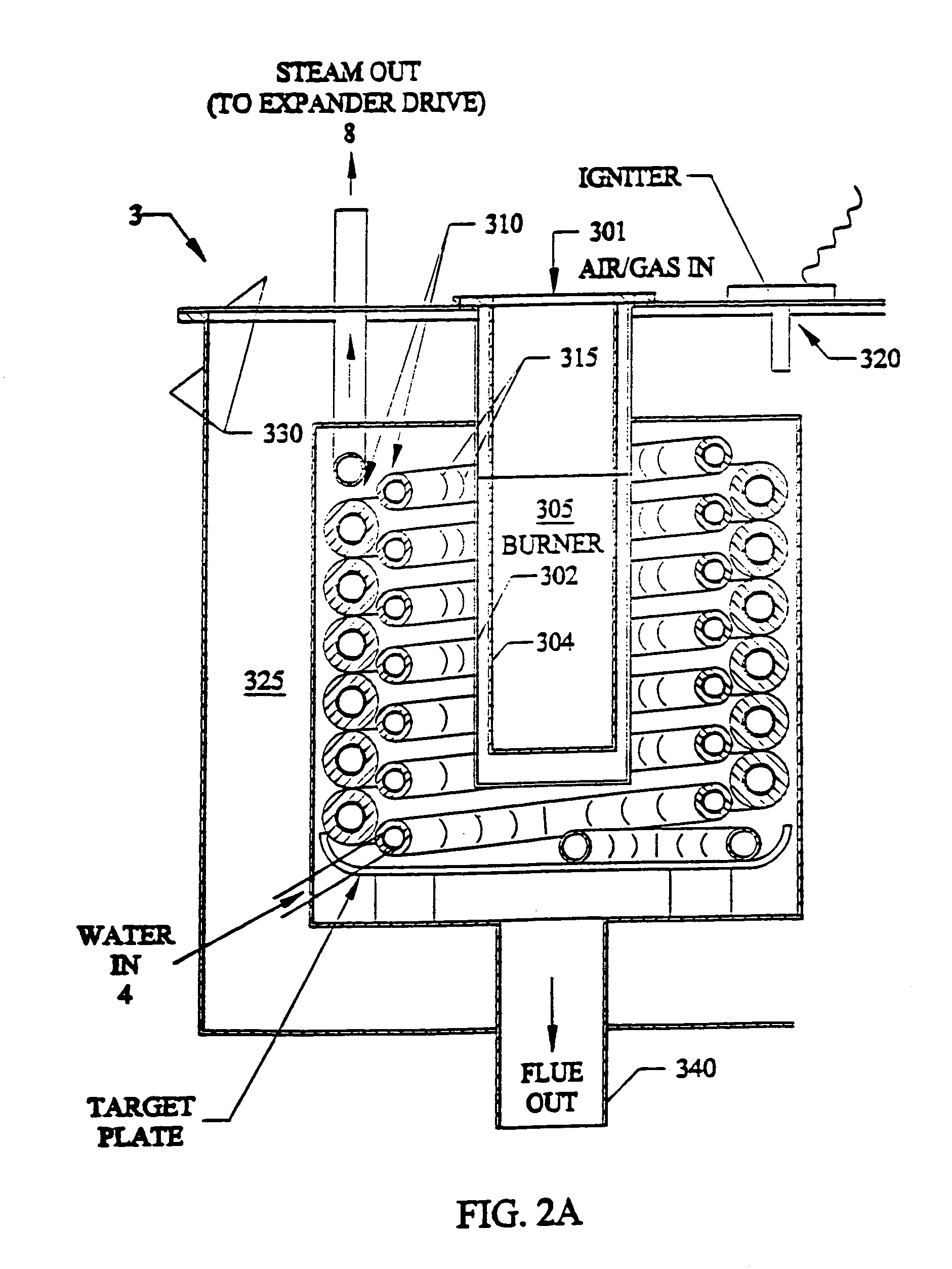
[0132]FIG. 13 shows a second preferred embodiment 1000 for heat generation using a closed loop steam generator system 1200, 1400, 1500, 1600, 1700. The steam generator(boiler 8) 1100 referenced above in FIGS. 2–3 turns water into steam by burning a fuel source (22FIG. 1) such as natural gas, propane, and any vaporous fuel. Generated steam having a temperature of approximately 280 to approximately 1000 degrees, and a pressure range of approximately 100 to approximately 600 psi. The generated steam has an efficiency rating of turning water into steam of up to approximately 98%, with flue gases being up to the remaining approximately 2%. The steam enters a steam to water condenser exchanger 1200(10FIG. 7) where the steam is changed back to water back into the heat(steam) generator by high pressure condensate return pump 1300 (5FIG. 9).

[0133]Operation of novel closed loop heat cycle. From the condenser heat exchanger 1200 water passes to hot water circulator 1400(such as off-the-shelf w...

embodiment 2000

[0136]FIG. 14 shows a third preferred embodiment 2000 for powering an air-conditioner unit using the novel steam generator 2100, expander 2400(8FIGS. 5A, 5B, 6) and steam condenser 2200 of the invention, which is a vaporous fuel supplied air conditioner. The steam generator 2100 referenced above in FIGS. 2A–2B turns water into steam by burning a fuel source such as natural gas, propane, and any vaporous fuel. Generated steam having a temperature of approximately 280 to approximately 1000 degrees, and a pressure range of approximately 100 to approximately 600 psi. The generated steam has an efficiency rating of turning water into steam of up to approximately 98%, with emitted flue gases being up to the remaining approximately 2%. The steam enters expander drive 2400(described above in reference to FIGS. 5A, 5B, and 6), which rotates output driveshaft 2450 which is mechanically connected to a direct drive compressor 2510 such as but not limited to a Copeland Inc. shaft driven compress...

embodiment 3000

[0139]FIG. 15 shows a fourth preferred embodiment 3000 for supplying electricity to any electrically powered device or system using the novel steam generator 3100(boiler 8FIGS. 2A, 2B), expander drive 3400(8FIGS. 5A, 5B and 6) and steam condenser 3200 of the invention. The steam generator 3100 referenced above in FIGS. 2A–2B turns water into steam by burning a fuel source 22 such as natural gas, propane, and any vaporous fuel. Generated steam having a temperature of approximately 280 to approximately 1000 degrees, and a pressure range of approximately 100 to approximately 600 psi. The generated steam has an efficiency rating of turning water into steam of up to approximately 98%, with emitted flue gases being up to the remaining approximately 2%. The steam enters expander drive 3400(described above in reference to FIGS. 5A, 5B and 6)), which rotates output driveshaft 3450 which is mechanically connected to an shaft driven electrical generator 3500 such as but not limited to SmartGen...


PUM


Abstract

A closed loop system for generating mechanical energy at high efficiencies. The system can have a heating source, a superheater, an expander, a receiver, an absorber, a desorber, and regenerator with pumps and controls. The superheater heats a working fluid (a refrigerant or steam). A positive liquid / vapor expander expands a low temperature refrigerant, or steam vapor to the saturated state (having both liquid and vapor parts) utilizing a low-pressure sub-atmospheric exhaust sink. An absorber, generates a low-pressure sub-atmospheric sink using chemosorption which involves the exothermic reaction / absorption of ammonia refrigerant in water. The desorber is used to reconstitute inlet vapor (for reuse) and the regenerator recovers heat generated by chemosorption. The system can meet electrical power needs for residences, businesses or office buildings. The system can supply electrical energy to power grids, and can be an alternative power generation plants.

Description

[0001]This invention claims the benefit of priority to U.S. Provisional Application No. 60 / 544,466 filed Feb. 13, 2004, and this invention is a Continuation-In-Part of U.S. patent application Ser. No. 10 / 414,672 filed Apr. 16, 2003 now abandoned, which claims the benefit of priority to U.S. Provisional Application Ser. No. 60 / 372,869 filed Apr. 16, 2002.FIELD OF INVENTION[0002]This invention relates to energy generation and power supply systems, and in particular to methods and systems that can meet all energy demands of a home or business or industrial use, and allows for excess electrical energy to be available to be sold over transmission grids, and in particular to expansive fluid systems and methods such as steam generation for generating electrical energy, and using co-generated heat byproducts for domestic hot water, room heating and swimming pool / spa heating, and for powering air conditioners and vehicles, and also to expansive methods and systems that use supertrope power p...

Claims


Application Information

Patent Timeline
Patent Type & Authority Patents(United States)
IPC IPC(8): F01K25/00F01K17/02F22B21/26F24D18/00
CPCF01K17/02F01K25/065F22B21/26Y02E20/14F24H2240/00F24D2101/10F24D2105/00F24D18/00F24D2103/13
Inventor RUGGIERI, FRANKLACKSTROM, DAVESALVAIL, NAPOLEON P.DRAAISMA, RUDOLPH N. J.
Owner RES SCI
Why Eureka
Try Eureka