System and method for model-based control of a building fluid distribution system

a technology of fluid distribution system and model-based control, which is applied in the direction of electric programme control, program control, instruments, etc., can solve the problems of affecting the test of building system, and rarely experiencing the design conditions of the terminal unit's terminal unit's terminal unit's terminal unit, etc., to achieve the effect of facilitating the testing of building system, facilitating management and maintenance, and accurate computation of flow loss coefficients

Active Publication Date: 2006-04-04
SIEMENS IND INC
View PDF17 Cites 14 Cited by
  • Summary
  • Abstract
  • Description
  • Claims
  • Application Information

AI Technical Summary

Benefits of technology

[0022]The present invention is implemented remotely from a central location instead of developing a “shrink-wrapped” software solution for the field locations. In the latter approach, the process of packaging high level mathematical functions and algorithms that are needed for model identification, software training, updates, and maintenance is potentially very challenging. By deploying the entire process of implementation of the proposed invention from a central server, the process is easy to manage and maintain. It also provides consistent outputs to buildings that are geographically distributed. The remote implementation process includes creating specific test vectors for a system, generating test code, simulating the building fluid distribution system, and developing an actual pressure distribution system control algorithm and program.
[0023]The system and method of the present invention enable the generation of controller instructions for a building system in an automatic manner.
[0024]The system and method of the present invention facilitate the testing of a building system to obtain data for more accurate computation of flow loss coefficients.
[0025]The system and method of the present invention provide improved modeling of a building system so more energy efficient control of the building system may be achieved.

Problems solved by technology

These fans consume energy in proportion to the product of the airflow rate and fan pressure.
However, the zones regulated by the terminal units rarely experience the design conditions.
Consequently, the zones typically require only a fraction of the design condition and this means that the pressure set point is significantly higher than what is required for operation of the building system most of the time.
The chapter entitled Automatic Control in the ASHRAE Handbook on HVAC Applications, 1995, states that excessive duct static pressure leads to poor system control, noise, and waste of electrical energy.
Furthermore, as the system ages, flow loss coefficients for a branch may change without detection.
Terminal unit closure assumes no leakage of air through a closed terminal unit; however, such an assumption is rarely accurate.
However, this proposal does not address how existing duct structure information may be collected for use in the solution and duct design software is not conducive for real time applications.
However, application of that approach to commercial properties does not appear feasible because large systems include multiple main duct segments and each one may have different airflow rates.
Another problem with this solution is that it requires a low flow rate through one open terminal while all other terminal units remain closed.
Such a condition is difficult to maintain in large building systems.
However, the handling of the error signals in those systems presented significant issues.
Establishing the fan set point at a level that results in a flow rate at one or more terminal units that is barely above its alarm level may inadequately serve a room in a typical commercial building.
In a research facility where air flow rate may also be important for safety reasons, such an operating condition is even more likely to be unacceptable.
Solutions that rely upon damper position signals rather than pressure or flow rate signals also present issues.
However, damper position sensors increase implementation costs and real time position measurements require complex signal processing and data analysis, especially with transient data.

Method used


Image

  • System and method for model-based control of a building fluid distribution system
  • System and method for model-based control of a building fluid distribution system
  • System and method for model-based control of a building fluid distribution system

Examples


Embodiment Construction

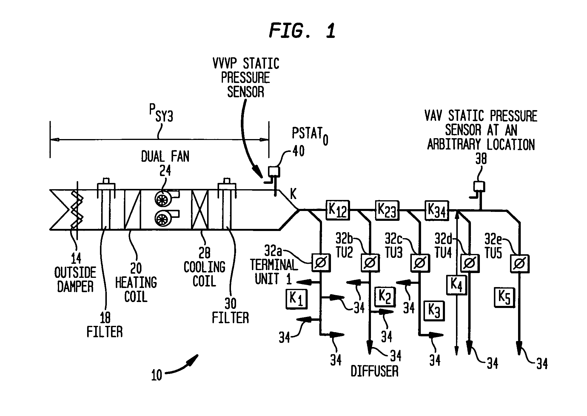
[0038]As noted above, an exemplary variable air volume (VAV) system is shown in FIG. 1. Outside air is drawn into system 10 through an outside damper 14, filtered through filter 18, and warmed, if necessary, by heating coil 20. A single or dual fan 24 pushes the air through cooling coil 28 for cooling, if required, and filtered again by filter 30 before being supplied to terminal units 32a, 32b, 32c, 32d, and 32e for distribution through diffusers 34 to zones serviced by the terminal units. Terminal units 32a–32e typically supply air at a constant temperature of 15 degrees Celsius for cooling and 22 degrees Celsius for heating. A fan controller regulates the speed of fan 24 to generate adequate pressure to overcome the resistance provided by the coils, filters, air ducts, and dampers. Typically, the pressure set point used by the fan controller to regulate the fan speed corresponds to an arbitrary location that is generally two-thirds of the distance to the terminal unit that is far...


PUM


Abstract

A system and method generates test vectors and a corresponding test program to manipulate terminal units in a building system so pressure and flow measurements correspond to independent modeling equations. The pressure and flow responses of the building system to the test program manipulation may be used to compute loss coefficients for the modeling equations. The modeling equations may then be updated with the computed loss coefficients so a building simulation may be performed. The simulated static pressure response of the modeling equations may be compared to measured static pressures to evaluate the sufficiency of the modeling equations.

Description

FIELD OF THE INVENTION[0001]This invention relates to control systems for building systems such as environmental systems and, more particularly, to systems for developing operational parameters for control of fluid distribution systems in buildings.BACKGROUND OF THE INVENTION[0002]Most commercial properties include a number of building systems that monitor and regulate various functions of the building for the comfort and well-being of the tenants. These building systems include security systems, fire control systems, and elevator systems. One prevalent and important building system is the environmental control system.[0003]An environmental control system is used to regulate the temperature and flow of air throughout a building. The air conditioning for a building typically includes one or more chillers for cooling air and one or more heaters for warming air. Fans distribute air conditioned by a chiller or heater into a duct system that directs the flow of air to the various rooms o...

Claims


Application Information

Patent Timeline
Patent Type & Authority Patents(United States)
IPC IPC(8): G06F19/00G05B13/00G05B17/02G05B23/02
CPCG05B17/02G05B15/02G05B2219/2642
Inventor AHMED, OSMANCASCIA, MARK A.COOGAN, JAMES JOSEPHKALORE, PANKAJ VIJAY
Owner SIEMENS IND INC
Why Eureka
Try Eureka