Bearing system for high-speed rotating machinery

Inactive Publication Date: 2006-04-11
RAINS JOHN K +1
View PDF24 Cites 63 Cited by
  • Summary
  • Abstract
  • Description
  • Claims
  • Application Information

AI Technical Summary

Benefits of technology

[0017]Bearing systems of the invention can comprise a double ball bearing system that includes two angular contact, anti-friction ball bearings mounted in opposite ends of an elongated cylinder, each carrying thrust in one direction only. The elongated cylinder can include a radially extending flange at one end that engages stationary housing members to carry the thrust load of the rotating assembly in both directions. The elongated cylinder can be supplied with two circumferential grooves, each of which carries an elastic member, such as an O-ring. These elastic members can be made of a temperature resistant rubber such as Viton. This elongated cylinder, containing the angular contact anti-friction ball bearings and O-ring seals can be insertable into a bore in a turbocharger bearing housing that is provided with an annular coolant water jacket that surrounds the elongated cylinder so the outside diameter of the elongated cylinder, when inserted into the bearing housing, forms the inner boundary of the coolant water jacket and the elastic members act as seals for closure of the coolant water passage. The unique arrangement of these components allows coolant to flow over the middle portion of the elongated cylinder, thus providing cooling for both the anti-friction ball bearings and the O-ring seals. In this bearing system, the O-ring elastic members also act as radial springs and allow minor orbital excursions of the elongated cylinder that occur as a result of residual unbalance in the rotating assembly, thus allowing the rotor to rotate about its mass center.
[0018]A preferred embodiment of this invention is one where the anti-friction ball bearings are of the full complement type that do not use a cage to space the balls.

Problems solved by technology

Early attempts to use ball bearings were unsuccessful in that sufficient durability could not be achieved.
However, the high rotational speed of the collar attached to the shaft resulted in a high thrust frictional loss which, in addition to the frictional losses of the sleeve bearings, resulted in a substantial total frictional loss for the complete bearing system.
In this bearing system, however, the differential speed between the sleeve bearing and rotor is the very high rotative speed of the rotor.
Since sleeve bearing frictional losses are proportional to the square of the differential rotating speed, this system has an inherent higher frictional loss than a full-floating sleeve bearing system.
The residual imbalance in the rotor forces the non-rotating cylinder to move orbitally, causing the mating surfaces to be subject to fretting.
Thus a solid film lubricant must be placed between the mating surfaces to mitigate the fretting problem; however, this problem remains an inherent disadvantage with this type of non-rotating cylinder system and contributes to a limited service life in the field.
This bearing system has proven to be very satisfactory for commercial use in high-speed turbochargers; however, it requires a supply of pressurized lubricant from the engine lubricating system and, historically, th

Method used


Image

  • Bearing system for high-speed rotating machinery
  • Bearing system for high-speed rotating machinery
  • Bearing system for high-speed rotating machinery

Examples


Embodiment Construction

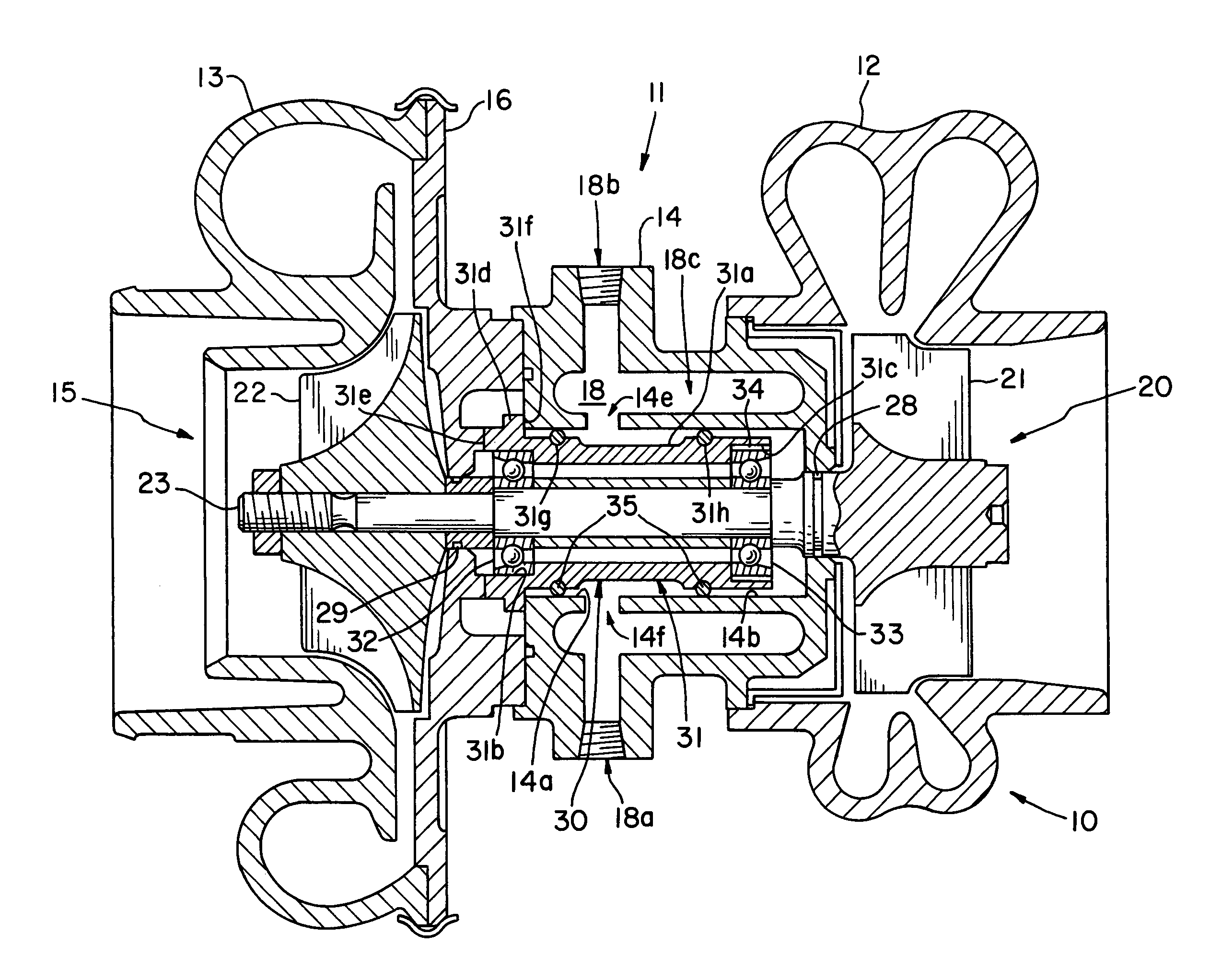
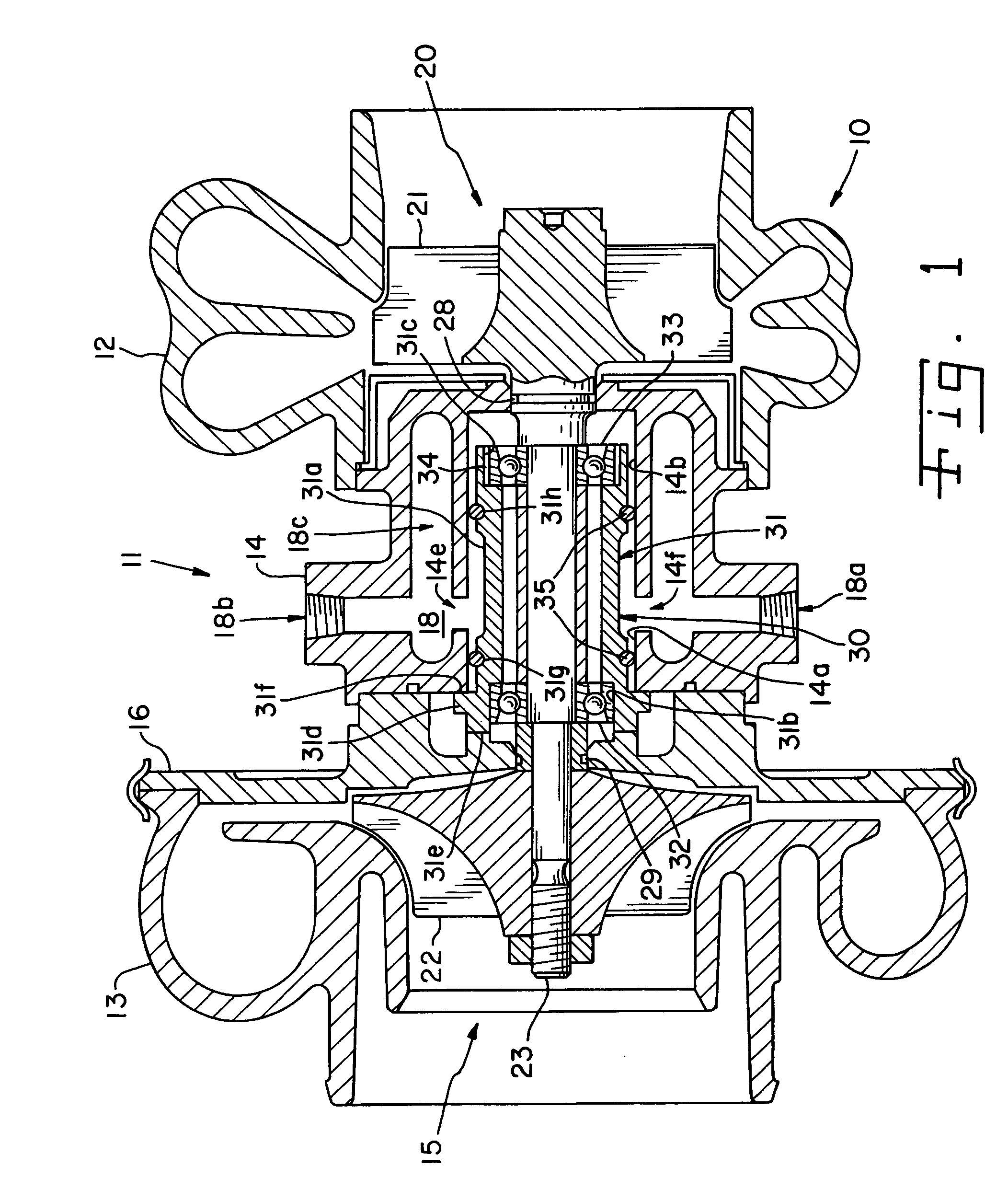
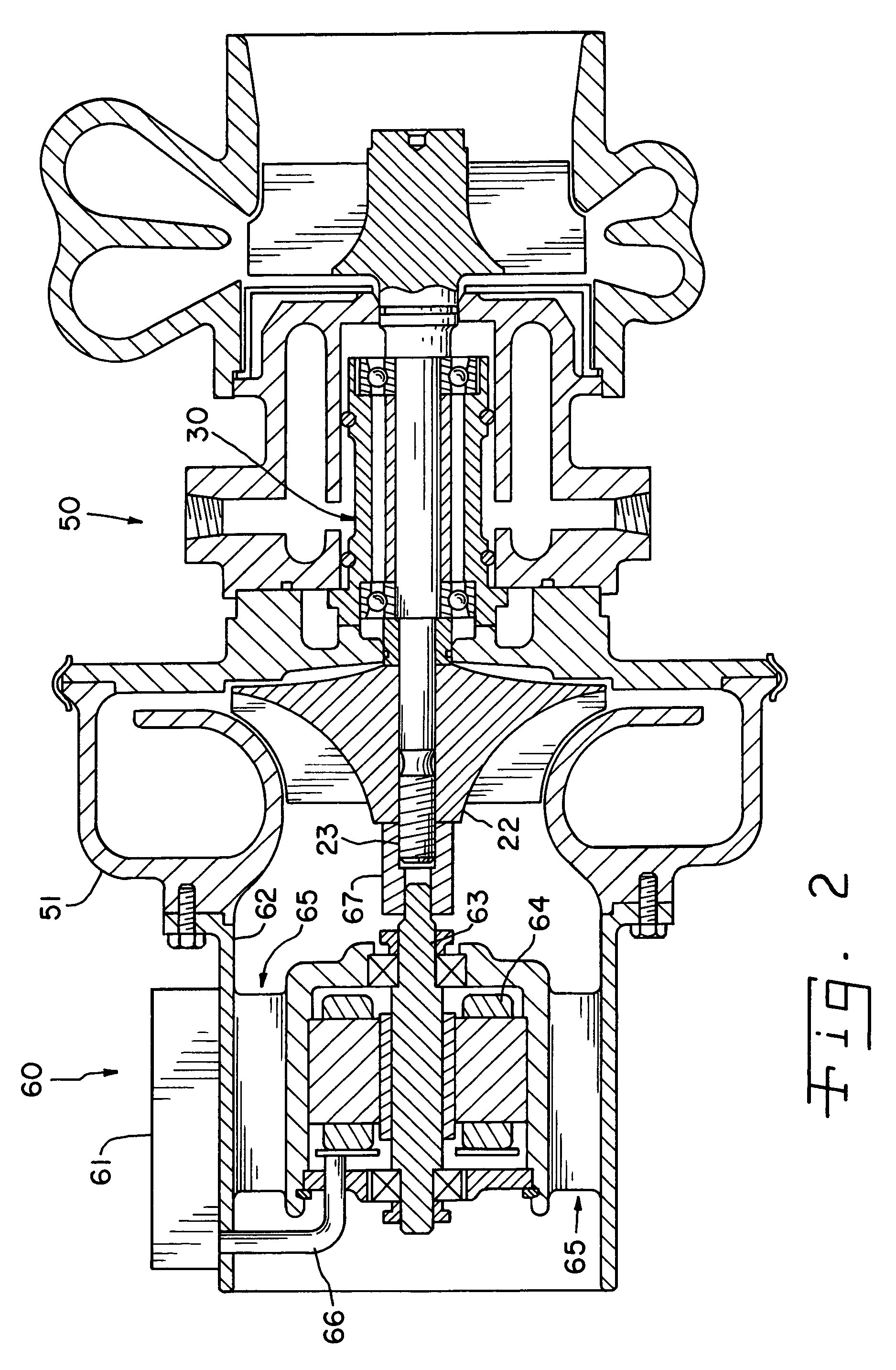
[0023]The bearing system of this invention is adapted to support, within a stationary element of a machine, a high-speed rotating shaft. A turbocharger 10, as illustrated in FIG. 1, is one example of a machine in which the invention may be advantageously employed, and the more detailed description of the invention that follows is in the context of the turbocharger, as illustrated in FIG. 1, and a motor-assisted turbocharger, as illustrated in FIG. 2.

[0024]As set forth above, FIG. 1 illustrates a turbocharger 10 of the type that is frequently used to supply charge air to the cylinders of an internal combustion engine. As well known in the art, the turbocharger 10 has a stationary housing 11, comprised of an exhaust gas volute 12, a compressor casing 13 and bearing housing 14 that encompasses the rotating assembly 20. The rotating assembly 20 is driven by the action of exhaust gas from an internal combustion engine (not shown) directed from the exhaust gas volute through the turbine w...


PUM


Abstract

A bearing system for a turbocharger shaft includes an elongated bearing carrier with two anti-friction ball bearings mounted in its ends and with a radially extending flange at one end that cooperates with stationary housing portions and carries thrust loads of the rotor in both directions. The elongated bearing carrier is supported within the housing by axially spaced elastic supports which permit the rotating assembly to rotate about its mass center and provide a shock and vibration cushion. The elongated bearing carrier and housing cooperate to provide a coolant cavity which communicates with the outside periphery of the elongated bearing carrier between the axially spaced elastic supports, which also act as coolant seals between the elongated bearing cavity and the bearing housing.

Description

RELATED APPLICATIONS[0001]This application is a continuation-in-part of application Ser. No. 09 / 978,935, filed Oct. 16, 2001 now abandoned, application Ser. No. 10 / 158,310, filed May 30, 2002 now U.S. Pat. No. 6,739,845, and application Ser. No. 10 / 369,801, filed Feb. 20, 2003 now U.S. Pat. No. 6,877,901.FIELD OF THE INVENTION[0002]This invention relates to bearing systems for machinery with shafts that rotate at high speeds and are exposed at one end to high temperatures, such as turbochargers used on internal combustion engines.BACKGROUND OF THE INVENTION[0003]Turbochargers for internal combustion engines have been widely used on both diesel and gasoline engines for many years. A great deal of effort was expended in the early years of turbocharger development to produce a bearing system that exhibited sufficient durability to make a small size turbocharger commercially viable. Early attempts to use ball bearings were unsuccessful in that sufficient durability could not be achieved...

Claims


Application Information

Patent Timeline
IPC IPC(8): F04B17/00F02B33/44F16C19/04F16C27/00F01D15/10F01D25/16F02BF02B37/10F02B39/10F02C7/06F04D25/04F04D29/04F04D29/056F04D29/059F04D29/66F16C19/52F16C19/54F16C27/04F16C27/06F16C35/06F16C35/077F16C37/00F16D31/02
CPCF01D15/10F01D25/164F02B37/025F02B37/10F02B39/005F02B39/10F02B39/14F02C7/06F04D25/04F04D29/0563F04D29/059F04D29/668F16C27/066F16C35/061F16C35/077F16C37/007F16C19/548F01D25/16F16C2360/24Y02T10/144F05D2220/40Y10S384/901Y02T10/12F04D25/024F04D25/0606
Inventor WOOLLENWEBER, WILLIAM E.MEYER, JON A.
Owner RAINS JOHN K
Why Eureka
Try Eureka