Method and apparatus for monitoring heart function in a subcutaneously implanted device

a technology methods, applied in the field of implantable medical devices, can solve the problems of relatively invasive procedures, inability to repeat the same measurement exactly the same way, and so as to reduce the power requirements of the device, improve the efficiency of the device, and improve the effect of the received energy

Active Publication Date: 2006-04-25
MEDTRONIC INC
View PDF19 Cites 275 Cited by
  • Summary
  • Abstract
  • Description
  • Claims
  • Application Information

AI Technical Summary

Benefits of technology

[0016]For an alternative heart and blood flow monitoring signal, an active ultrasound sensor (with a frequency between 1 and 10 MHZ) may be provided as a single transmitter/receiver incorporated in the implanted device or carried by a lead extending from the device. The single transmitter/receiver may be operated in a burst send/receive mode such that a burst of sound waves of a desired frequency are transmitted to a targeted heart location and the reflected echoes are received by the same transmitter/receiver. Alternatively, a separate receiver may be incorporated in the device or carried by a lead extending from the device such that the transmitter may continuously send an ultrasonic signal that is continuously received by the receiver. Ultrasonic sensor positioning and anchoring are important in optimizing the received energy and in repeatability of measurements made. Interference from dense bones, such...

Problems solved by technology

In addition, a hemodynamic signal may allow the physician to continue to track the heart rate when the subcutaneous ECG becomes difficult to interpret due to electrical interference from artifacts such as loss of electrode contact, muscle noise or electromagnetic interference (EMI).
While clinical examinations are useful for patient assessment, they are limited in that they reflect the patient's condition only at a particular time on a particular day.
Repeated examinations may be performed but the same measurement...

Method used


Image

  • Method and apparatus for monitoring heart function in a subcutaneously implanted device
  • Method and apparatus for monitoring heart function in a subcutaneously implanted device
  • Method and apparatus for monitoring heart function in a subcutaneously implanted device

Examples


Embodiment Construction

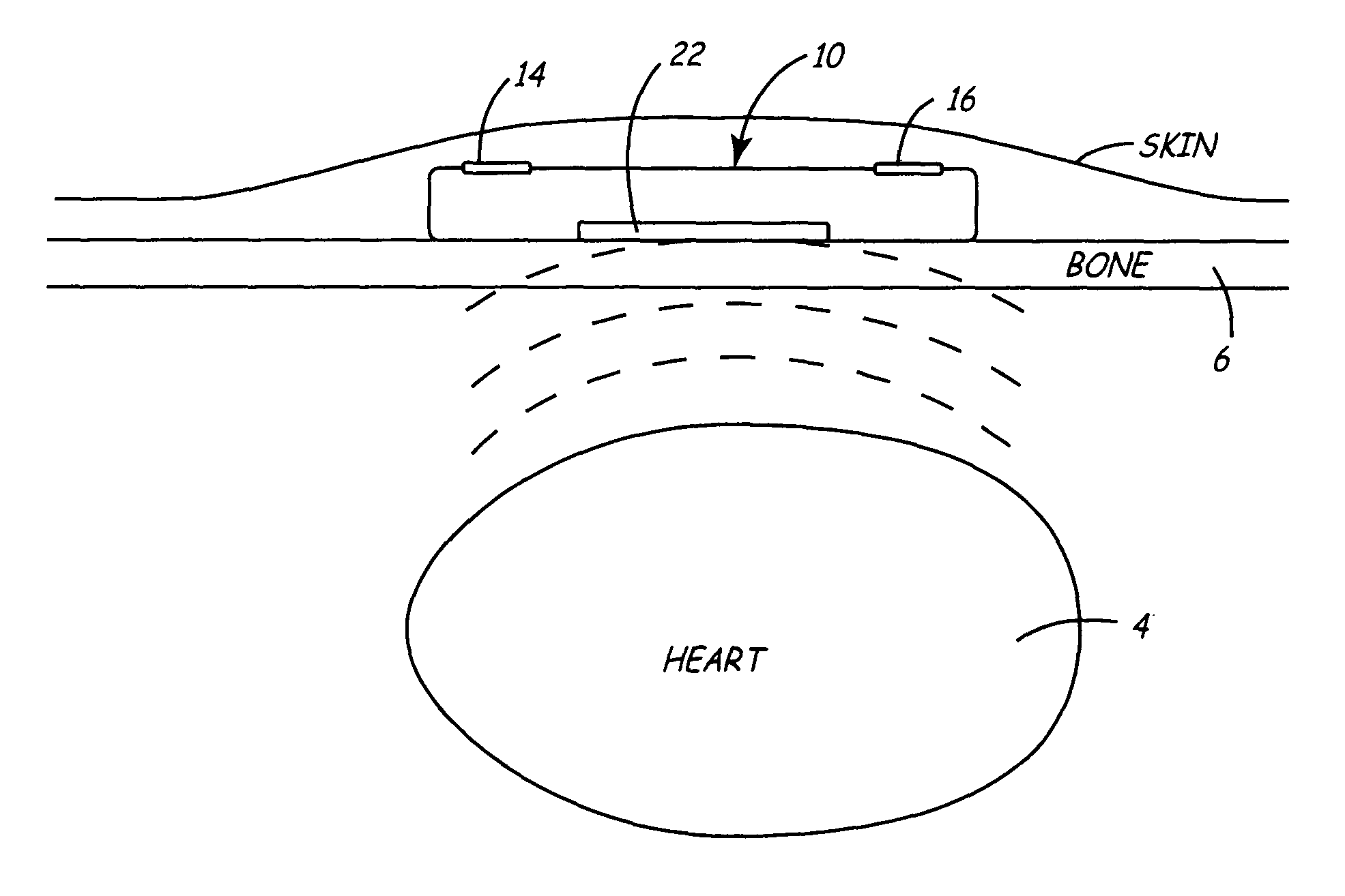
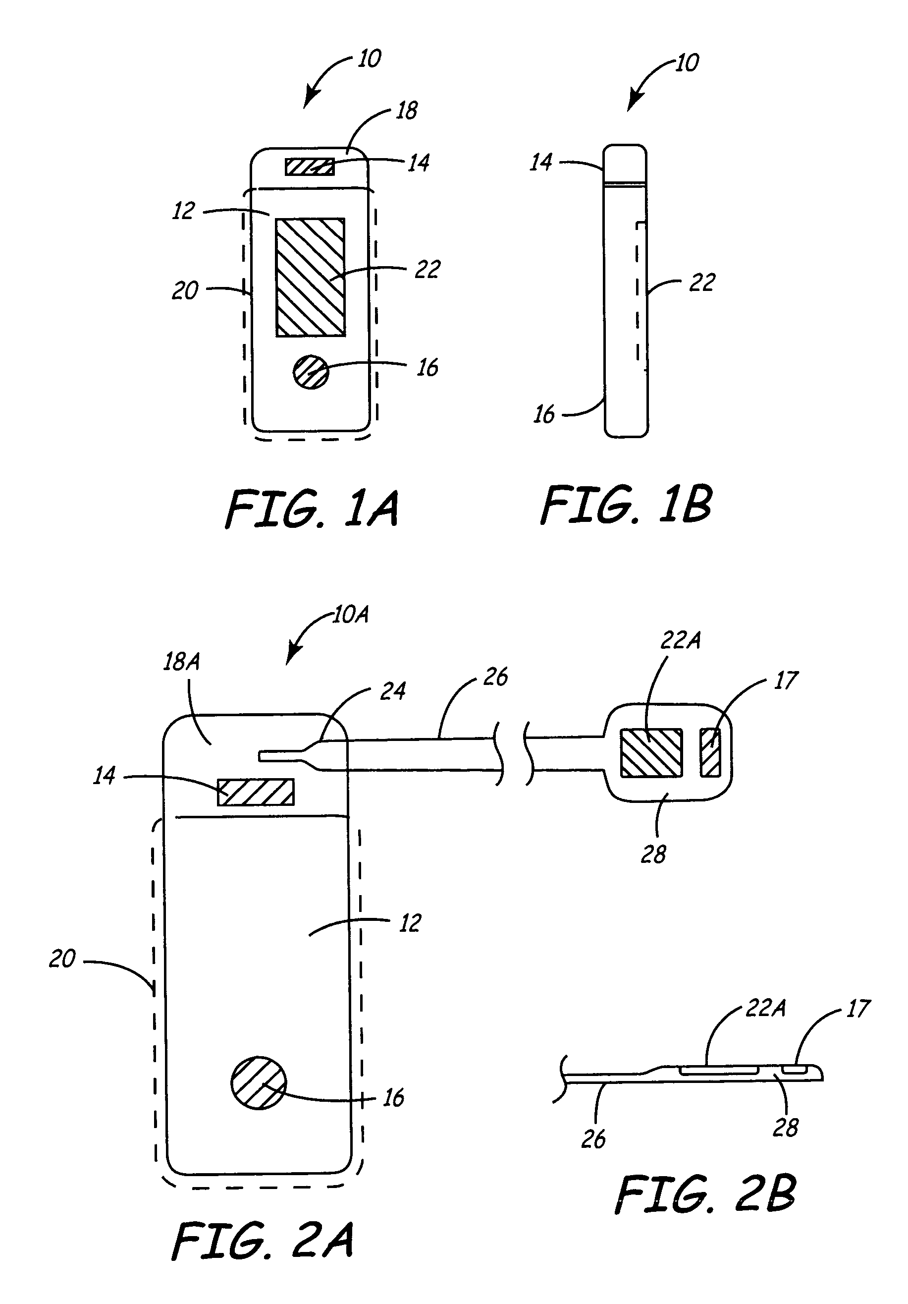
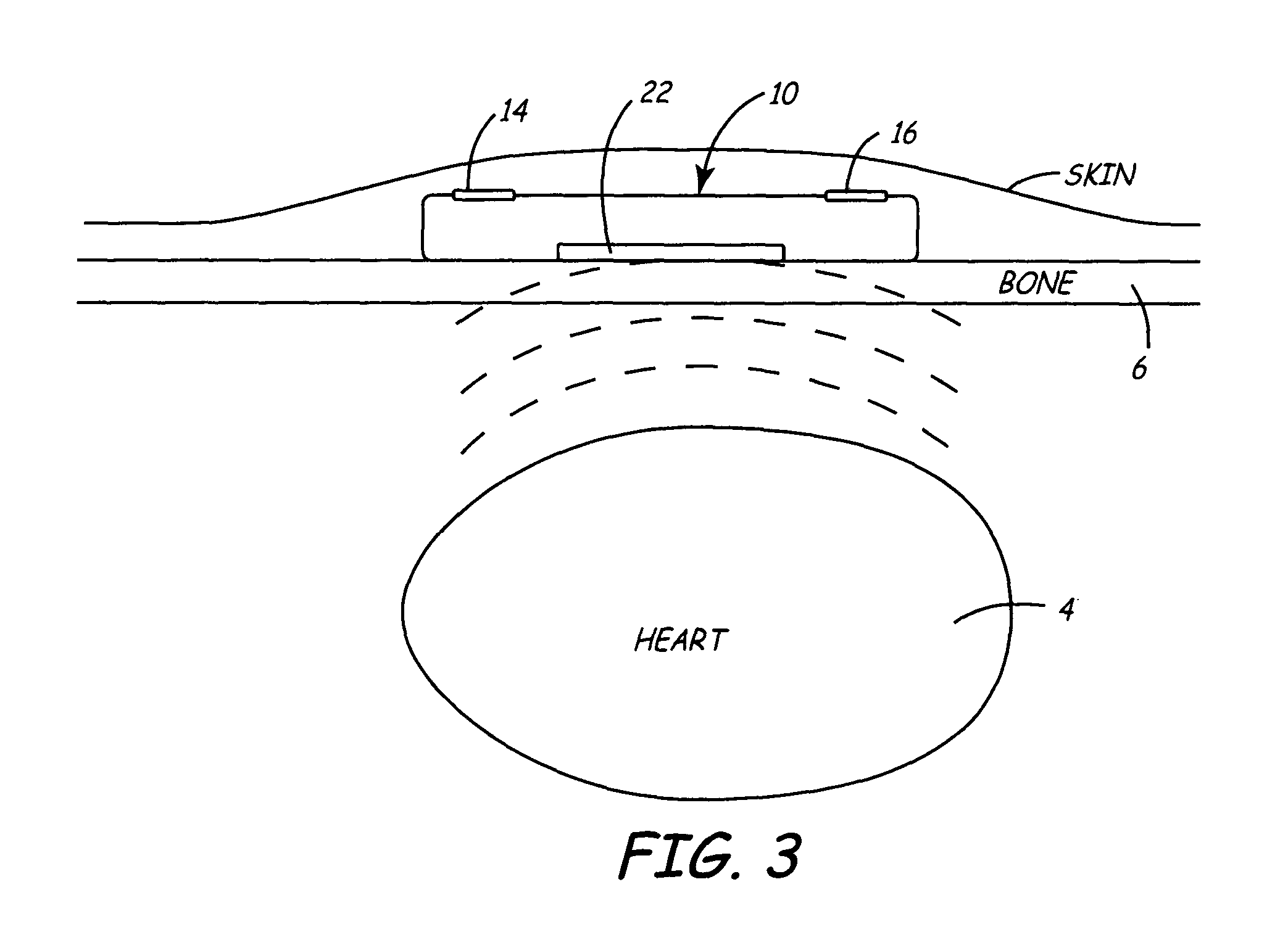
[0030]FIGS. 1A and 1B illustrate a front and side view of a minimally invasive implantable device 10 for chronically monitoring heart function. The size and shape of device 10 may be generally provided as disclosed in U.S. Pat. No. 5,987,352, issued to Klein et al., incorporated herein by reference in its entirety. The device 10 is provided with a hermetically sealed housing or “can”12 preferably formed from a biocompatible metal such as titanium and closed at one end by a plastic cap member 18. Cap member 18 may be formed of materials similar to those used for pacemaker connector blocks, such as polyurethane or epoxy. Housing 12 is provided with an insulative coating 20, indicated by dashed line, formed from an insulating material, such as a Parylene coating. Device 10 preferably includes at least two electrodes 14 and 16 for sensing a patient's subcutaneous ECG. Electrode 14 is formed from a biocompatible conductive metal such as platinum, iridium, titanium, or alloys thereof. Ele...


PUM


Abstract

A minimally invasive, implantable monitor and associated method for chronically monitoring a patient's hemodynamic function based on signals sensed by one or more acoustical sensors. The monitor may be implanted subcutaneously or submuscularly in relation to the heart to allow acoustic signals generated by heart or blood motion to be received by a passive or active acoustical sensor. Circuitry for filtering and amplifying and digitizing acoustical data is included, and sampled data may be continuously or intermittently written to a looping memory buffer. ECG electrodes and associated circuitry may be included to simultaneously record ECG data. Upon a manual or automatic trigger event acoustical and ECG data may be stored in long-term memory for future uploading to an external device. The external device may present acoustical data visually and acoustically with associated ECG data to allow interpretation of both electrical and mechanical heart function.

Description

CROSS-REFERENCE TO RELATED APPLICATION[0001]Cross-reference is hereby made to commonly assigned related U.S. Application, filed concurrently herewith, Ser. No. 10 / 376,063, entitled “APPARATUS AND METHOD FOR CHRONICALLY MONITORING HEART SOUNDS FOR DERIVING ESTIMATED BLOOD PRESSURE”.FIELD OF THE INVENTION[0002]The present invention relates to implantable medical devices and, in particular, the present invention relates to an implantable medical device subcutaneously implanted for monitoring the hemodynamic function of a patient's heart using an acoustical sensor.BACKGROUND OF THE INVENTION[0003]Chronic monitoring of heart function can provide valuable diagnostic information for a variety of cardiovascular conditions, including arrhythmias, heart failure, syncope or other autonomic system abnormalities, etc. For example, chronic monitoring of the ECG subcutaneously, using a device such as the Reveal® Insertable Loop Recorder available from Medtronic, Inc., can be useful in diagnosing i...

Claims


Application Information

Patent Timeline
IPC IPC(8): A61B5/04A61B5/00A61B5/0205A61B5/0215A61B5/0452A61N1/05A61N1/365A61N1/37
CPCA61B5/0031A61B5/0205A61B5/0215A61N1/05A61N1/36514A61B5/0452A61B5/7232A61N1/3702A61B8/0883A61B8/06A61B8/488A61B8/12A61B5/349
Inventor LEE, BRIAN B.
Owner MEDTRONIC INC
Why Eureka
Try Eureka