

Adsorbent for heat utilization system, adsorbent for regenerator system, regenerator system comprising the adsorbent, ferroaluminophosphate and method for production thereof
a technology of adsorbent and heat utilization system, which is applied in the direction of machine/engine, energy input, refrigeration machines, etc., can solve the problems of poor adsorption characteristic at low relative vapor pressure, inability to be used in constituting a regenerator system, and generalization said to be expensive, etc., and achieves favorable adsorption
- Summary
- Abstract
- Description
- Claims
- Application Information
AI Technical Summary
Benefits of technology
Problems solved by technology
Method used
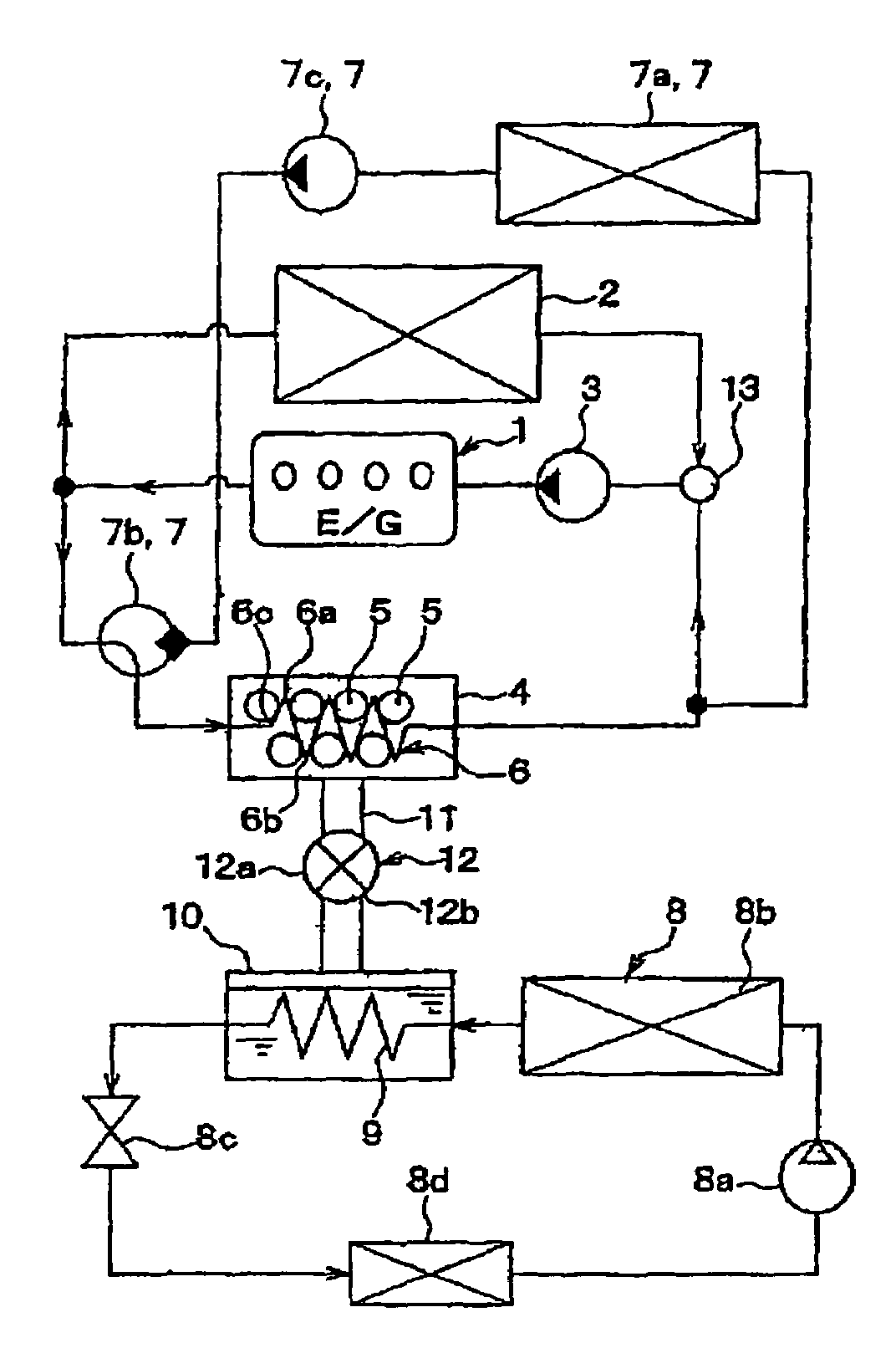
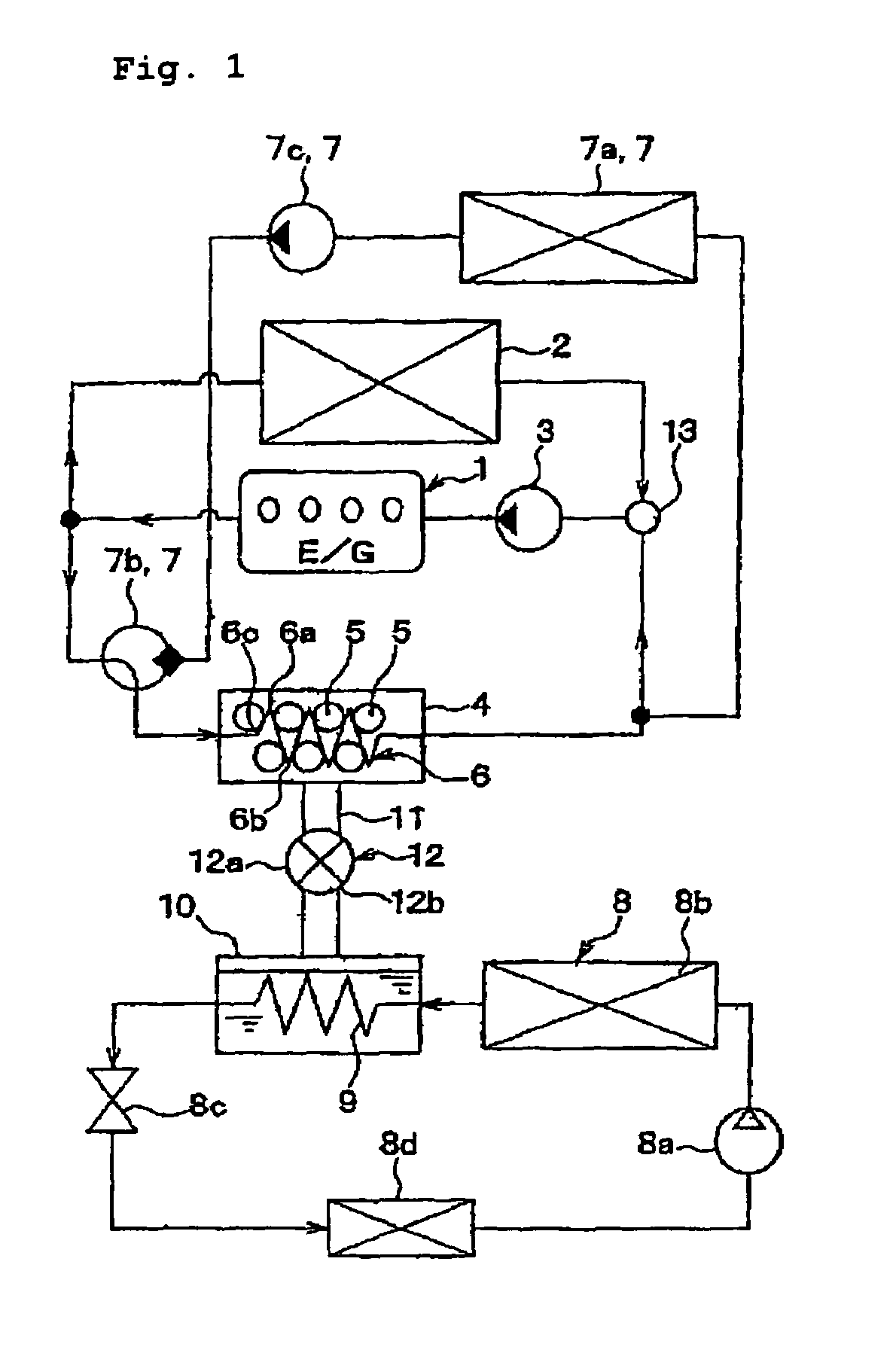
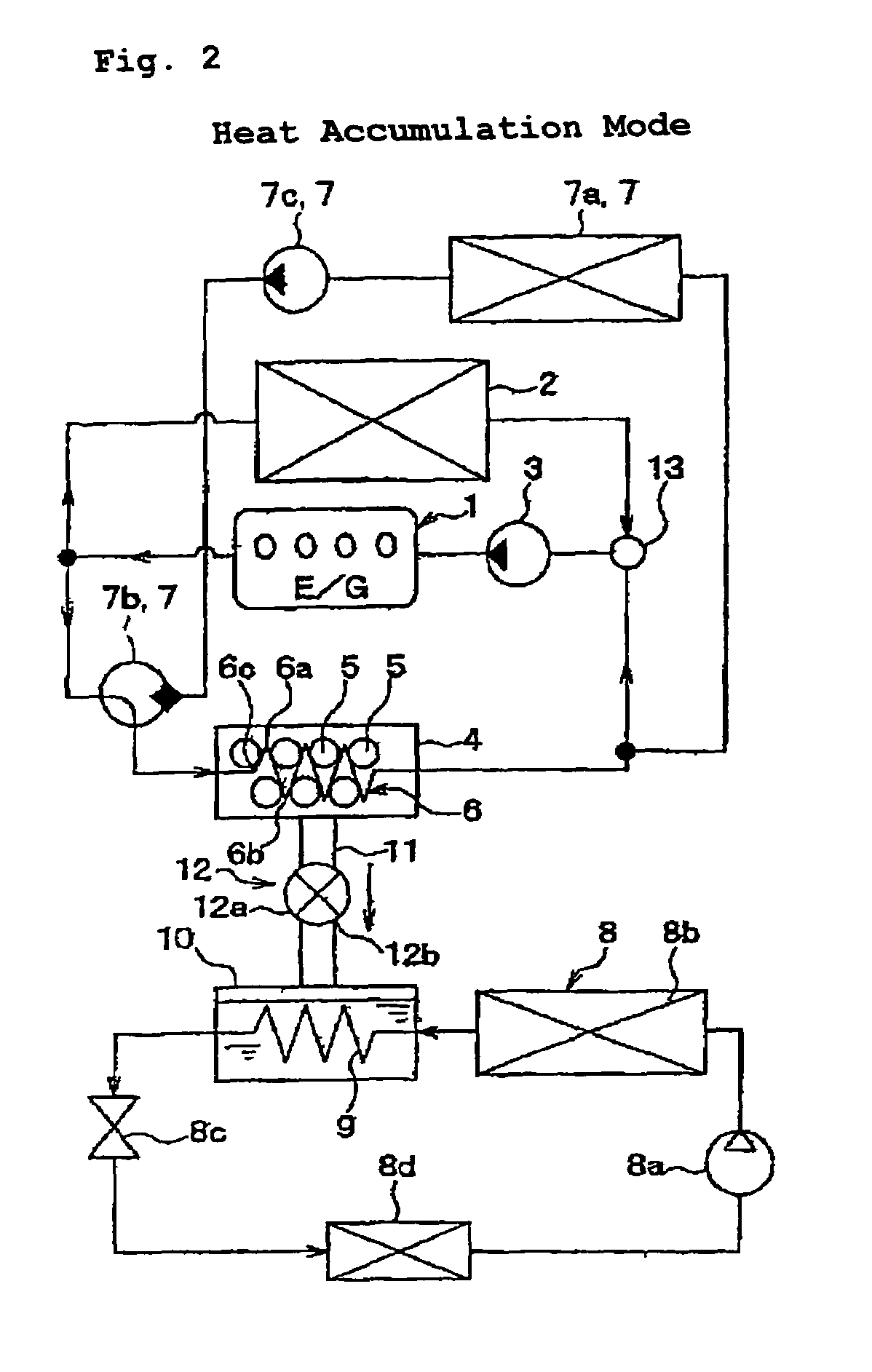
Image

Examples
example 1
[0204]Example 1 is to demonstrate FAPO-2 production by the use of morpholine and triethylamine as the template.
[0205]To a mixture of 28.05 g of water and 11.53 g of 85% phosphoric acid, gradually added was 6.8 g of pseudoboehmite (containing 25% water, manufactured by Condea), and stirred. This is liquid A. Apart from the liquid A, 2.78 g of ferrous sulfate 7-hydrate, 5.05 g of morpholine, 4.35 g of triethylamine and 29 g of water were mixed to prepare a liquid. This was gradually added to the liquid A, and stirred for 3 hours to prepare a starting reaction material having the following composition.[0206]0.2FeSO4:Al2O3:P2O5:1.16morpholine:0.86triethylamine:70H2O.
[0207]The starting reaction material was fed into a 200-cc stainless autoclave with a Teflon (registered trade name) inner cylinder therein, and reacted at 160° C. for 4 days while kept static. After thus reacted, this was cooled, its supernatant was removed through decantation, and the deposit was recovered. Thus recovered,...
example 2
[0232]Zeolite was produced under the same condition as in Example 1, for which, however, the template-containing zeolite that had been synthesized was calcined in nitrogen. Table 7 shows the data of XRD of the thus-obtained zeolite.
[0233]
TABLE 7Relative2θIntensity9.57810012.99719.814.0823.616.17816.117.89722.619.2044.020.79950.422.1913.322.6131.823.2583.225.10819.426.16115.127.9032.328.3924.329.8442.730.94624.531.32011.233.7452.134.8615.236.3082.343.3701.048.2281.149.3102.0
[0234]FIG. 9 is a water vapor adsorption isotherm of the zeolite, measured at 55° C. by the use of an adsorption isothermometer (Bellsorb 18 by Nippon Bell). Concretely, the sample was analyzed under the following condition: The temperature of air in a thermostat is 60° C.; the adsorption temperature is 55° C.; the initial pressure is 3.0 Torr; the number of pressure set point is 0; the saturated vapor pressure is 118.11 mmHg; the equilibrium time is 500 seconds.
example 3
[0235]The sample calcined in nitrogen in Example 2 was re-calcined in air under the same condition as in Example 1. Table 8 shows the data of XRD of the thus-obtained zeolite. It is understood that the re-calcined zeolite is almost the same as the zeolite in Example 1.
[0236]
TABLE 8Relative2θIntensity9.54710010.15758.112.75322.915.6055.516.9836.219.45352.520.39929.821.33914.722.75210.624.38334.225.6316.926.0764.026.69716.327.1814.227.94822.029.25222.630.64646.031.61617.832.48512.732.95220.533.7013.834.1732.635.1134.936.5487.738.2223.039.5744.140.2321.841.6192.842.7522.943.5972.046.2583.748.4993.649.1434.4
PUM
| Property | Measurement | Unit |
|---|---|---|
| temperature | aaaaa | aaaaa |
| temperature | aaaaa | aaaaa |
| temperature | aaaaa | aaaaa |
Abstract
Description
Claims
Application Information