Optical information recording medium, producing method thereof and method of recording/erasing/reproducing information

a technology of optical information and recording medium, which is applied in the manufacture of optical record carriers, record information storage, nuclear engineering, etc., can solve the problems of high error rate of recording signals, readout errors, and phase change optical recording medium, and achieve excellent weather resistance, reproducible effect, and excellent characteristics of repetitive recording

Inactive Publication Date: 2006-05-02
PANASONIC CORP
View PDF111 Cites 9 Cited by
  • Summary
  • Abstract
  • Description
  • Claims
  • Application Information

AI Technical Summary

Benefits of technology

[0036]According to a structure in which the barrier material is applied to a substrate side of the recording layer, an effect for suppressing the atomic diffusion and the chemical reaction between the recording layer and the protective layer is higher, thereby a cycle performance is enhanced. According to the structure in which the barrier material is applied to the side opposite to the substrate of the recording layer, the effect for enhancing a stability of rewrite performance is higher, thereby a reliability is enhanced. Not only the structure in which the barrier material is applied to both sides of the recording layer combines both characteristics, but also both performances are further enhanced.
[0075]According to another aspect of the present invention, a method for producing an optical information recording medium includes the steps of: forming a recording layer having reversibly changeable optical characteristics, and forming a Ge-containing layer comprising either one selected from the group consisting of GeXN and GeXON as a main component, where X is an element as described above. The Ge-containing layer is produced by reactive sputtering with a target including at least Ge and X in a mixed gas comprising a rare gas and nitrogen. This makes it possible to produce efficiently an optical information recording medium having excellent weather resistance and excellent characteristics in repetitive recording.

Problems solved by technology

However, it is known that the phase change optical recording medium has the following problems.
That is, the signal is repeatedly rewritten, thereby the reflectance of the medium is reduced, an amplitude of the signal is gradually reduced, or a jitter value at a marked position of a recording mark becomes larger, thereby an error rate of the recording signal becomes higher.
Therefore, when the signal is reproduced, a readout error is occurred.
Accordingly, there is such a problem that a possible times of rewriting is limited.
Furthermore, another cause is that one part of the protective layer material is chemically reacted with the recording layer.
For example, under an environment having a high temperature and a high humidity, there is another problem that a peeling is occurred.
Thereby, there is further problem that oxide such as SiO2, Ta2O5, Al2O3 and the like and nitride such as Si3N4, AlN and the like cannot be applied to a dielectric layer material.

Method used


Image

  • Optical information recording medium, producing method thereof and method of recording/erasing/reproducing information
  • Optical information recording medium, producing method thereof and method of recording/erasing/reproducing information
  • Optical information recording medium, producing method thereof and method of recording/erasing/reproducing information

Examples


example 1

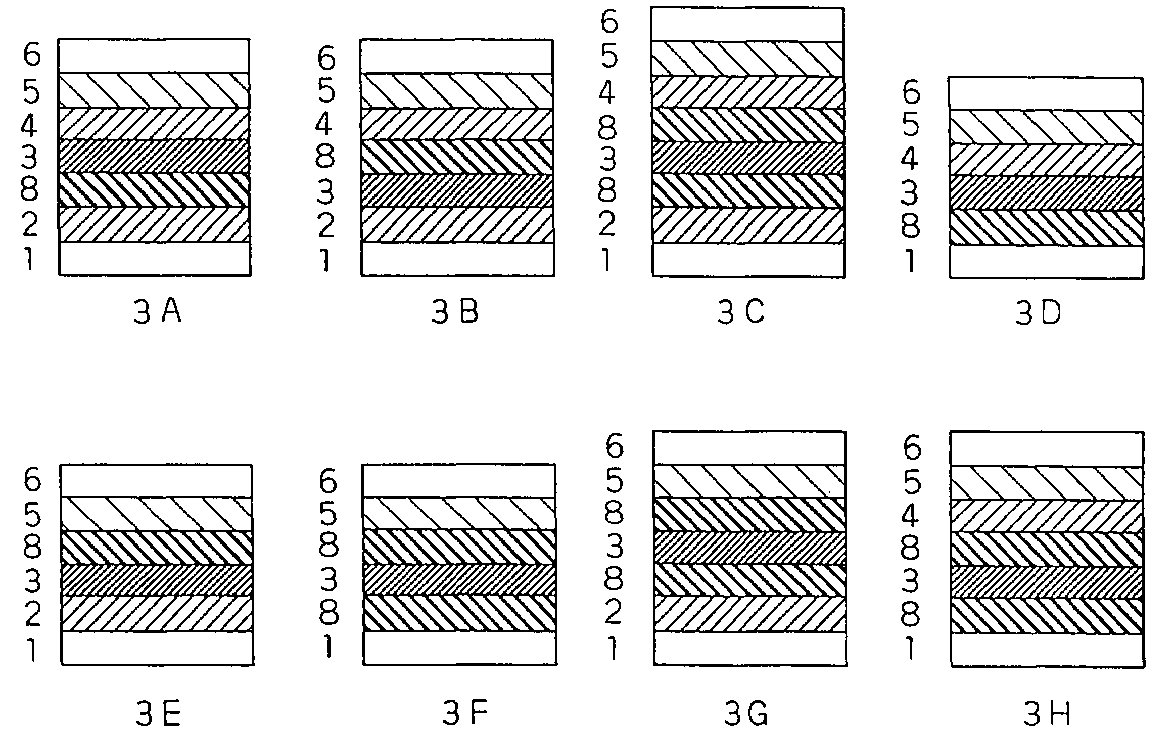
[0227]The optical disks having the layer structure shown in FIGS. 3A and 3B (a disk (1) and a disk (3) in a table 4) are made on a experimental basis. The recording layer 3 comprises a phase change material whose main component is a Ge2Sb2.3Te5 alloy, and the dielectric protective layers 2 and 4 comprises a ZnS—SiO2 film. When the film is formed, the gas is supplied in such a manner that each total pressure of the Ar gas becomes 1.0 mTorr and 0.5 mTorr, respectively, and each of the powers DC1.27 W / cm2 and RF6.37 W / cm2 is introduced into the negative electrode 55, respectively. Furthermore, when the reflecting layer (AlCr) 5 is formed, the Ar gas is supplied in such a manner that the total pressure becomes 3.0 mTorr, thereby the power DC 4.45 W / cm2 is introduced.

[0228]In the disk (1), after the dielectric protective layer is formed, sequentially, the barrier layer 8 is formed. In the disk (3), after the recording layer 3 is formed, sequentially, the barrier layer 8 is formed. In thi...

example 2

[0231]All the protective layers at the substrate side of the disk (1) in Table 4 in the example 1 are changed to the Ge—N layer or the Ge—N—O layer, thereby a disk (5) is formed (accordingly, the Ge—N protective layer or the Ge—N—O protective layer whose thickness is 91 nm is formed at the substrate side of the recording layer). Furthermore, all the protective layers at the reflecting layer side of the disk (3) in Table 4 are changed to the Ge—N layer or the Ge—N—O layer, thereby a disk (6) is formed (accordingly, the Ge—N protective layer or the Ge—N—O protective layer whose thickness is 25.2 nm is formed at the reflecting layer side of the recording layer). The repeating characteristic of disks (5) and (6) is examined by the same method as the example 1. Both of them can similarly obtain the result ⊚. That is, the Ge—N layer or the Ge—N—O layer can be formed in such a manner that the Ge—N layer or the Ge—N—O layer can obtain a thickness necessary for the protective layer. Furtherm...

example 3

[0232]Next, the recording layer 3 comprises a phase change material whose main component is a Ge2Sb2.3Te5 alloy, when the barrier layer 8 is formed, Sb is used as the target, and the mixture of Ar and nitrogen is used as the sputter gas. On the above condition, the films comprising the structure shown in FIGS. 3A and 3B are formed (a disk (2), a disk (4)). In this case, the film thickness of each layer is same as the thickness in the above case that Ge is used as the target. The spatter gas pressure of the barrier layer 8 is 20 mTorr, and the partial pressure ratio of Ar to nitrogen in the sputter gas is 3 to 1. In this case, the result of the repeating characteristic is shown in disk numbers (2) and (4) in Table 4.

[0233]According to Table 4, compared to the case that Ge is used as the target so that the film is formed, although the number of repeatable times is inferior, better repeating characteristic can be obtained than the comparative example.

[0234]

TABLE 4Result 3 of comparing ...


PUM

PropertyMeasurementUnit
thicknessaaaaaaaaaa
thicknessaaaaaaaaaa
thicknessaaaaaaaaaa

Abstract

The present invention provides an optical information medium having excellent weather resistance and repeating characteristics. The optical information medium has a barrier layer between a protective layer and a recording layer. The barrier layer includes GeN or GeON, and at least one element selected from the group consisting of Al, B, Ba, Bi, C, Ca, Ce, Cr, Dy, Eu, Ga, H, In, K, La, Mn, N, Nb, Ni, Pb, Pd, S, Si, Sb, Sn, Ta, Te, Ti, V, W, Yb, Zn and Zr.

Description

[0001]This application is a divisional of application Ser. No. 09 / 390,228, filed Sep. 3, 1999, now U.S. Pat. No. 6,821,707 which is a continuation-in-part of application Ser. No. 08 / 815,301, filed Mar. 11, 1997 now abandoned and Ser. No. 09 / 050,762, filed Mar. 30, 1998, now abandoned which application(s) are incorporated herein by reference.BACKGROUND OF THE INVENTION[0002]1. Field of the Invention[0003]The present invention relates to an optical information recording medium provided with an optically detectable information recording layer, the producing method thereof and a method of recording / erasing / reproducing information.[0004]2. Description of the Prior Art[0005]A recording material thin film layer comprising a metal thin film and an organic thin film is formed on a disc-shaped or a card-shaped substrate. A high energy beam focused on a micro light spot having a submicron order diameter is irradiated onto the recording material layer, thereby a local variation is generated on ...

Claims


Application Information

Patent Timeline
Patent Type & Authority Patents(United States)
IPC IPC(8): C23C14/34G11B7/0045G11B7/005G11B7/0055G11B7/006G11B7/007G11B7/013G11B7/24G11B7/243G11B7/257G11B7/258G11B7/26
CPCG11B7/00454G11B7/0052G11B7/00557G11B7/006G11B7/243G11B7/257G11B7/26G11B7/24G11B7/007G11B7/00718G11B2007/25715G11B7/24085G11B2007/2571G11B2007/25713G11B7/2531G11B7/2533G11B7/258G11B7/2585G11B7/2595G11B2007/24312G11B2007/24314G11B2007/24316G11B2007/25706G11B2007/25708Y10S430/146
Inventor OTOBA, MAYUMIYAMADA, NOBORUKAWAHARA, KATSUMIOHTA, HIROYUKIOHNO, EIJINAGATA, KEN'ICHI
Owner PANASONIC CORP
Why Eureka
Try Eureka