
Track link production method and track link produced by the same

Inactive Publication Date: 2006-05-09
KOMATSU LTD
View PDF7 Cites 34 Cited by
  • Summary
  • Abstract
  • Description
  • Claims
  • Application Information

AI Technical Summary

Benefits of technology

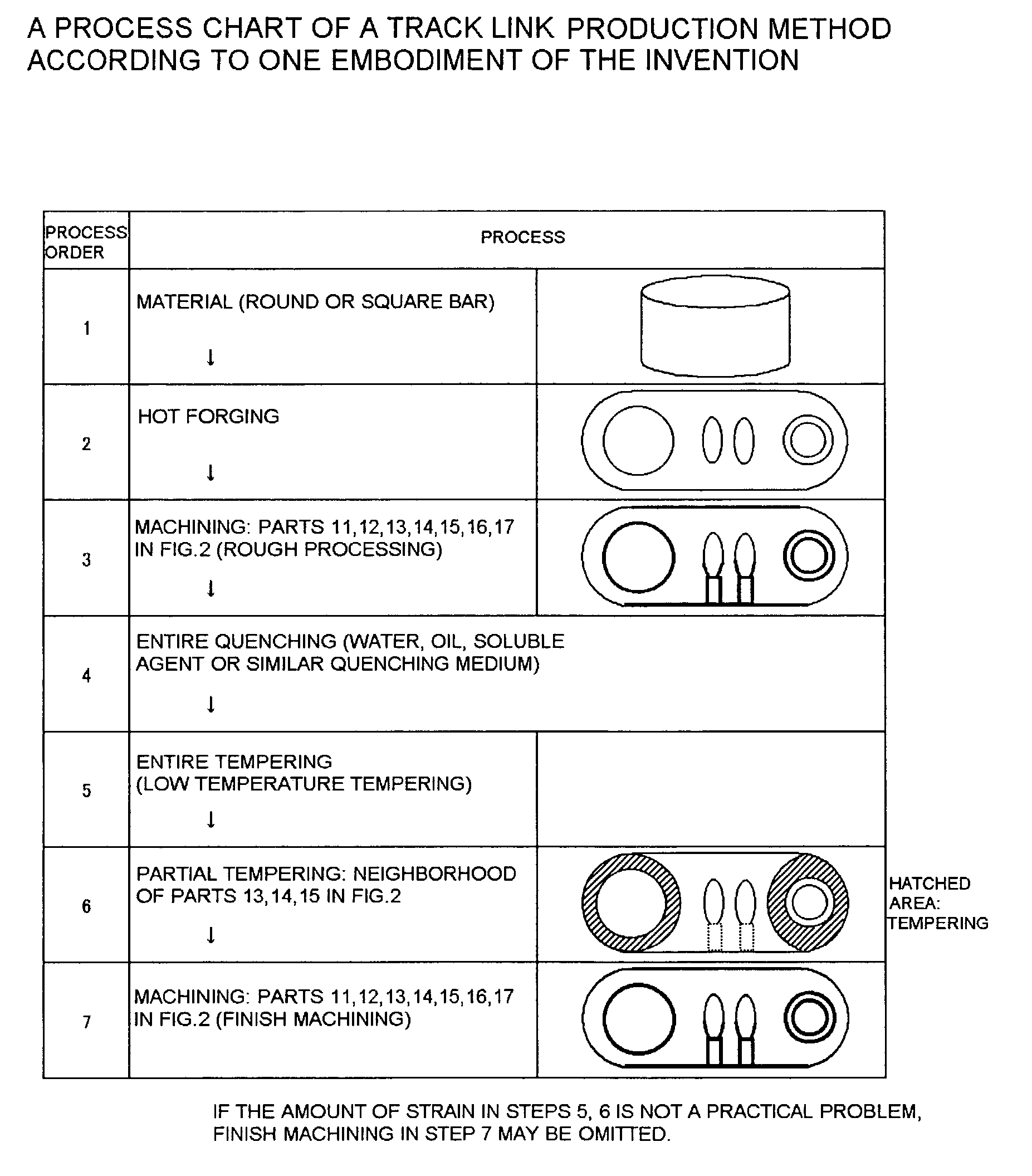
[0012]According to the first aspect, by the heat treatment process in which quenching and low temperature tempering treatment is applied to a whole link material after hot forging, the whole green body of the link material is hardened, resulting in formation of a deep hardened zone on the wheel tread surface of the link. Accordingly, the wear life of the track link can be significantly improved. In addition, since the desired machining is applied to the link material before the heat treatment process, that is, the link material in an easily processable condition with comparatively low hardness, accuracy defects due to difficult processing and poor cost performance can be prevented. Further, since after the heat treatment process, tempering (partial tempering) is applied to some of the parts of the link material which have undergone the machining process, the some parts including at least parts where high dimensional accuracy is required and parts where delayed failure may be caused by high stress due to press-fitting of a pin or bushing, strain inevitably caused by the heat treatment can be removed and the link material is softened and brought into an easily processable condition. As a result, finish machining after the partial tempering can be easily and reliably performed and dimensional accuracy can be ensured at low cost while preventing delayed failure.
[0014]According to the second aspect, since wear resistance can be ensured for a long time owing to the high-strength, hardened zone formed in the area extending from the wheel tread to the center core, the wear life of the track link can be markedly improved.
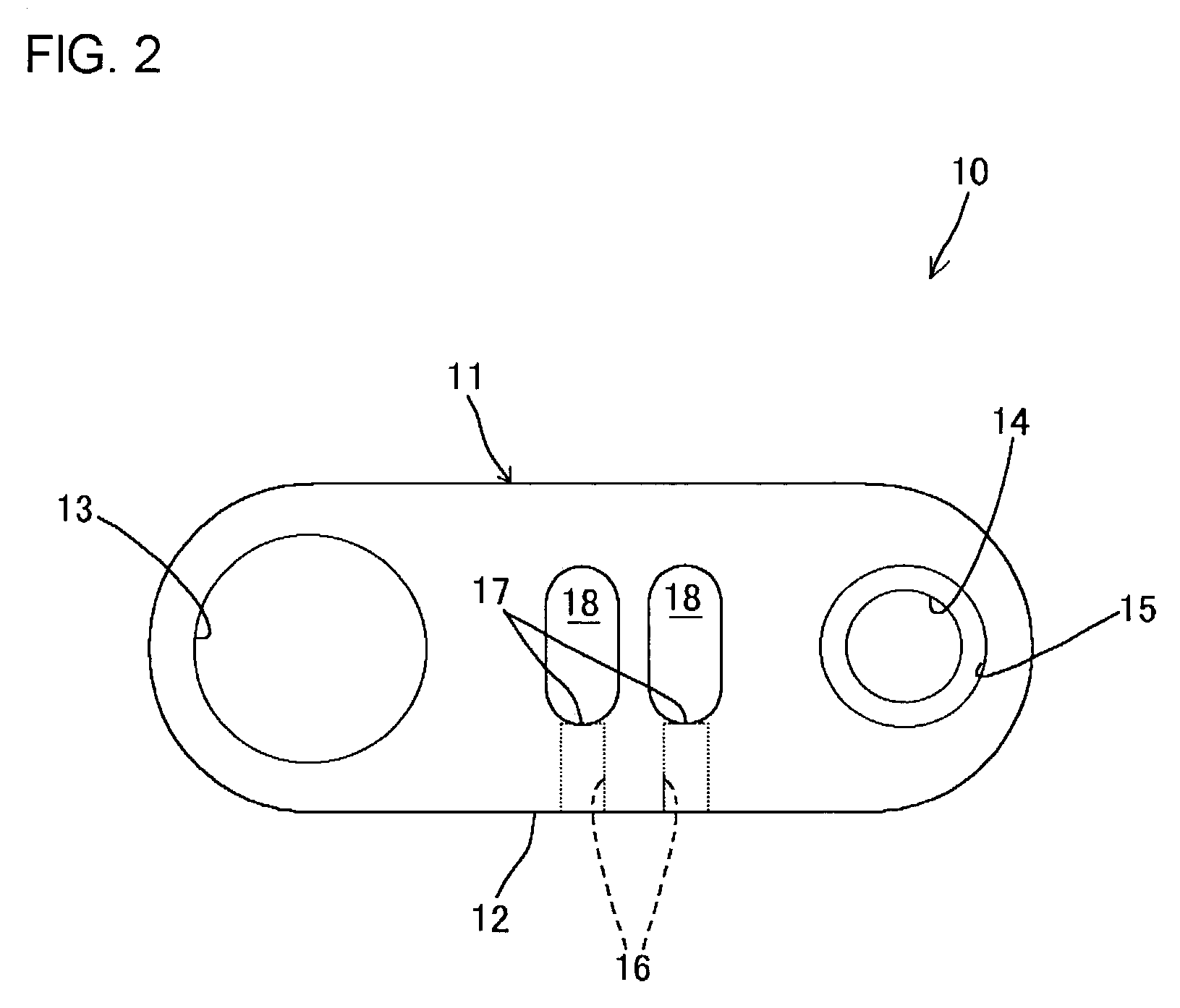
[0016]According to the third aspect, since the hardness of the areas around the pin hole and bushing hole is HRC40 or less, delayed failure due to high stress caused by press-fitting of a pin or bushing can be prevented, finish machining can be easily and reliably carried out, and dimensional accuracy can be assured at low cost.

Problems solved by technology

Of these machined parts, the wheel tread part is susceptible to wear caused by earth and sand because high surface pressure would be imposed on the wheel tread part with earth and sand trapped between the wheel tread part and the track roller.
A track link usually loses its function and ends its service life when the wear of the wheel tread proceeds so that the flange of the track roller interferes with the track link or when the wheel tread becomes so thin that it is not strong enough to bear the weight of the vehicle any longer.
However, the surface hardening method such as ordinary induction quenching and tempering process has the disadvantage that the hardened layer to be formed with the method is relatively shallow (about 15 mm), no matter how good the hardenability of the used material.
If the heated surface region is deepened with the intention of obtaining a deeper hardened layer, heating time becomes longer with the result that the temperature of the wheel tread part becomes too high, leading to an increase in crystal grain size and consequently a decrease in the toughness of the wheel tread part.
As a result, a layer (i.e., the so-called soft zone) having hardness lower than the hardness already attained by thermal refining is formed as indicated by IQT (Induction QuenchingTempering) product line in the hardness distribution comparative graph of FIG. 4, so that the strength of the link material becomes insufficient and, in consequence, peeling of the hardened layer occurs.

Method used


Image

  • Track link production method and track link produced by the same
  • Track link production method and track link produced by the same
  • Track link production method and track link produced by the same

Examples


Embodiment Construction

[0023]Reference is now made to the accompanying drawings to describe a track link production method and a track link produced by the same according to a preferred embodiment of the invention. The present embodiment is associated with one application of the invention to a bulldozer which is a kind of track type (caterpillar tread type) vehicles incorporated in construction equipment.

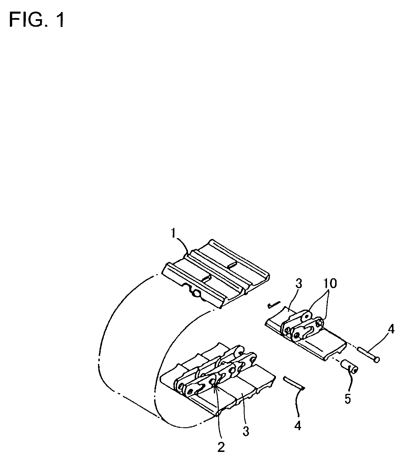
[0024]FIG. 1 shows an exploded perspective view of a crawler belt according to the present embodiment of the invention. FIG. 2 is an outside view of a track link.

[0025]The bulldozer according to the present embodiment has a vehicle body (not shown) and crawler belts 1 which are respectively disposed at both sides of the vehicle body, for forward and backward traveling and turning of the vehicle body. Each crawler belt 1 includes a track chain 2 wound around an idler (not shown) and a sprocket (not shown), and track shoes 3 clamped to the track chain 2 by bolts (not shown) and nuts (not shown). Rotation of...


PUM

PropertyMeasurementUnit
Temperatureaaaaaaaaaa
Grain sizeaaaaaaaaaa

Abstract

There are proposed a track link production method capable of providing markedly improved wear life with good cost performance and a track link produced by this method. To this end, the track link production method includes a heat treatment process (Steps 4, 5) of applying quenching and low temperature tempering treatment to a whole link material after hot forging (Step 2), and is designed such that desired machining is applied to the link material (Step 3) before the heat treatment process (Steps 4, 5) and such that after the heat treatment process (Steps 4, 5), tempering (Step 6) and finish machining (Step 7) are sequentially applied to some of the parts which have undergone the machining process, the some parts including at least parts where high dimensional accuracy is required.

Description

TECHNICAL FIELD[0001]The present invention relates to a method of producing a track link which is a component of an endless track crawler belt for use in construction equipment such as hydraulic excavators and bulldozers and a track link produced by the same.BACKGROUND ART[0002]For example, a crawler belt for the undercarriage of a bulldozer is constituted by track shoes, track links, coupling pins, track bushings and seals. Each track shoe is fastened to laterally paired track links with bolts and nuts (see FIG. 1). Each track link has (a) a wheel tread which comes in rolling contact with a track roller, (b) a shoe mounting surface to which a track shoe is attached, (c) a pin hole for receiving a coupling pin inserted therein, (d) a bushing hole for receiving a track bushing inserted therein, (e) a seal counter bore to which a seal is fit, (f) shoe bolt holes for receiving track shoe clamping bolts inserted therein, and (g) shoe nuts bearing surface on which track shoe clamping nut...

Claims


Application Information

Patent Timeline
IPC IPC(8): F16C7/00B21L5/00B62D55/20C21D1/06B21J5/00B62D55/205B21K23/02B23P15/00B62D55/00B62D55/32C21D1/00C21D1/18C21D9/00
CPCB21J5/00B21K23/02B23P15/00C21D1/18C21D9/0087B62D55/32C21D2261/00
Inventor OKAWA, KAZUHIDESUNADA, HIROSHI
Owner KOMATSU LTD
Learn More