Tissue treatment device and method

a treatment device and tissue technology, applied in the field of tissue treatment devices and methods, can solve the problems of heat-induced blisters, unnecessarily high epidermis peak power, and build-up of debris, and achieve high peak power, high fluence, and high peak power

Inactive Publication Date: 2006-05-09
CUTERA
View PDF158 Cites 73 Cited by
  • Summary
  • Abstract
  • Description
  • Claims
  • Application Information

AI Technical Summary

Benefits of technology

[0013]The pulse duration has been shown to have significant clinical implications. A short pulse, typically in the sub-5 ms, range creates high peak powers because high fluence is required to deliver enough energy to achieve the proper clinical endpoint. High peak power tends to heat the epidermis. Longer pulses result in lower peak power.
[0014]Shorter wavelengths, such as 694 nm, do not penetrate deeply into the patient's skin so, some believe, that it may be desirable, with such shorter wavelengths, to use a convex window pressing against the skin to shorten the path from the window to the hair tissue as is taught by U.S. Pat. No. 5,735,844 patent. It has been found that by the use of longer wavelengths which are still absorbed by melanin, such as 800 to 1200 nm, it is not necessary for the window of the radiation source to press against the patient's skin to effectively irradia...

Problems solved by technology

One problem associated with a contact cooling window in direct contact with the skin is debris build up.
Although larger diameter hairs will be selectively heated with short pulses, defi...

Method used


Image

  • Tissue treatment device and method
  • Tissue treatment device and method
  • Tissue treatment device and method

Examples


Embodiment Construction

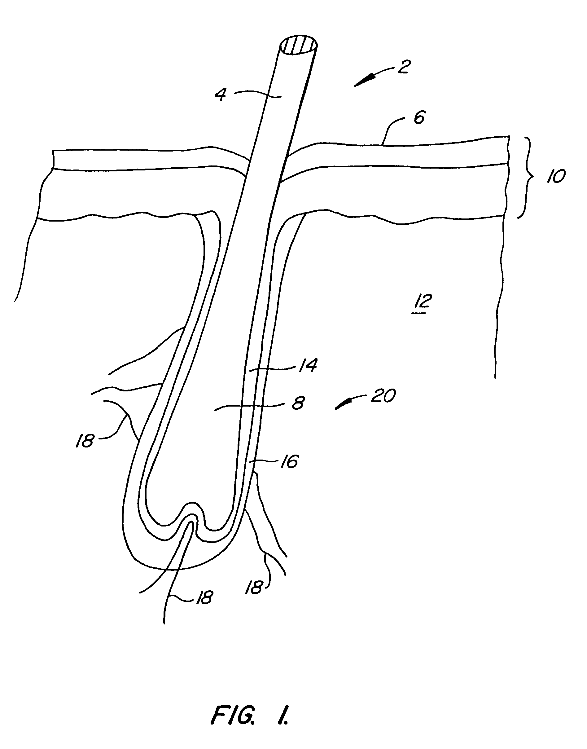
[0032]FIG. 1 illustrates, in simplified form, a hair 2 including a shaft 4 extending above skin surface 6 and a root 8 extending below the skin surface. The root 8 passes through epidermis 10 into dermis 12 with the base of the root being about 4 mm below surface 6. Root 8 is housed within hair follicle 14, hair follicle 14 being surrounded by various tissues including connective tissue sheath 16 and blood vessels 18. The various tissues closely surrounding root 8 and connected with the growth of hair 2, including hair follicle 14 and connective tissue sheath 16, are collectively referred to as hair tissue 20 in this application.

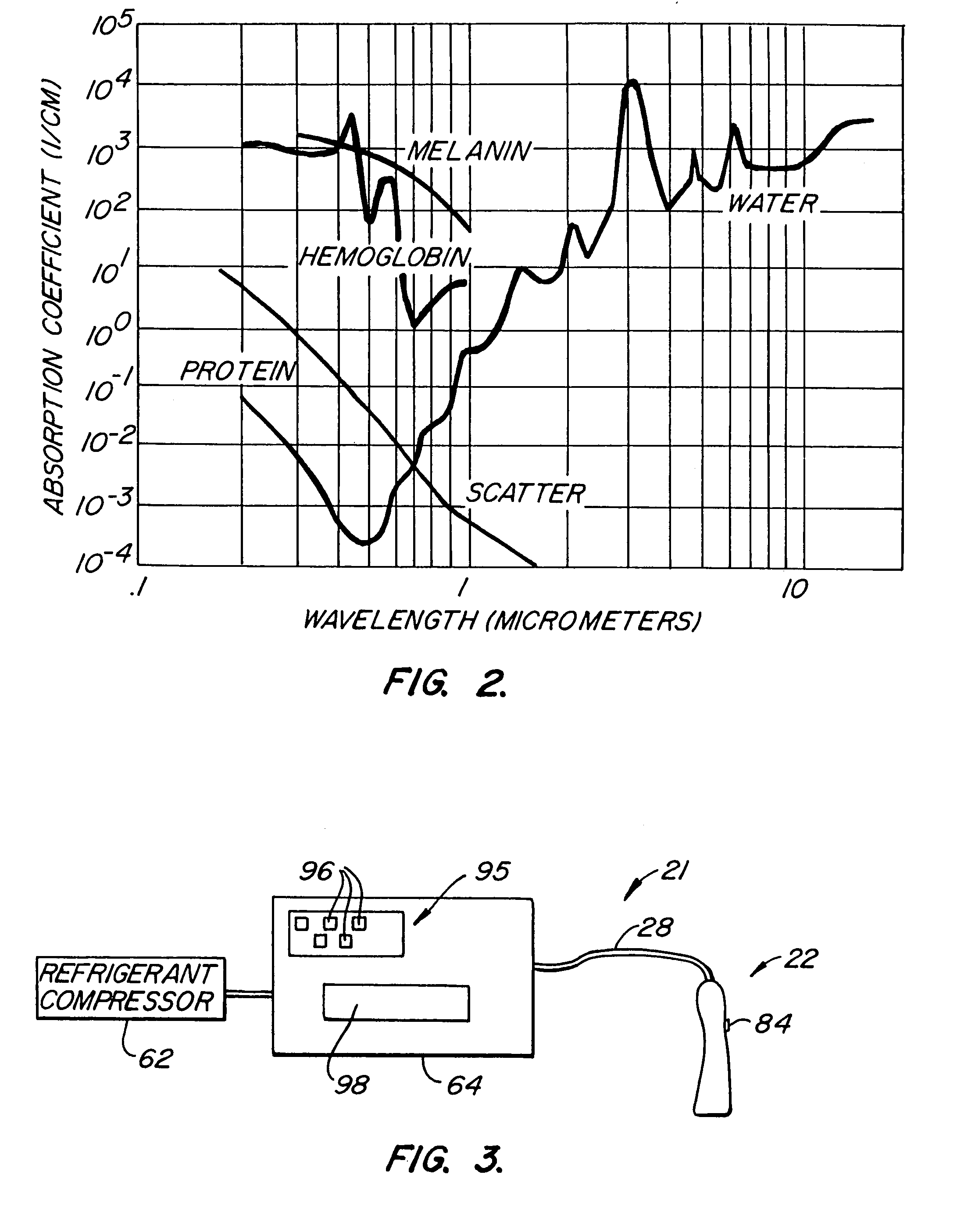
[0033]Because melanin is also present in epidermis 10, with darker skin types having more melanin than lighter skin types, it is important that the wavelength be long enough so that absorption is low for the moderate concentrations in melanin in the epidermis to permit most of the light to pass through to the root 8 and hair tissue 20 where melanin concentra...


PUM


Abstract

A hair removal device (22) includes a cooling surface (34) which is used to contact the skin (6) prior to exposure to hair tissue-damaging laser light (74) passing from a radiation source (36) through a recessed window (46). The window is laterally offset from the cooling surface and is spaced apart from the cooling surface in a direction away from the patient's skin to create a gap between the window and the skin. The window preferably includes both an inner window (46) and an outer, user-replaceable window (48). The laser-pulse duration is preferably selected according to the general diameter of the hair.

Description

CROSS-REFERENCE TO RELATED APPLICATIONS[0001]This application is a continuation of and claims priority from U.S. patent application Ser. No. 09 / 998,821, filed Nov. 15, 2001, now issued U.S. Pat. No. 6,666,856, which is a divisional of and claims priority from U.S. patent application Ser. No. 09 / 270,118 filed Mar. 15, 1999, now U.S. Pat. No. 6,383,176 which is related to a Provisional patent application Ser. No. 60 / 124,450, and Provisional patent application Ser. No. 60 / 124,709, both filed on Mar. 15, 1999, the disclosures of which are incorporated herein by reference.BACKGROUND OF THE INVENTION[0002]Use of light to denature very specific kinds of tissue has been called wavelength-selective photo-thermolysis. The use of lasers for this purpose has been well described in the literature. See, for example, R. G. Wheland, “Laser-assisted hair removal”, Lasers in Dermatology, Vol. 15, pp. 469–477, and references cited. By choosing a laser with the right wavelength and energy per unit area...

Claims


Application Information

Patent Timeline
IPC IPC(8): A61B18/18A61B18/00A61B18/20
CPCA61B18/203A61B2018/00005A61B2018/00023A61B2018/00476A61B2018/00041A61B2018/00452A61B2018/00458A61B2018/00029
Inventor CONNORS, KEVIN P.GOLLNICK, DAVID A.SASNETT, MICHAEL W.
Owner CUTERA
Why Eureka
Try Eureka