Microfabrication method based on metal matrix composite technology

a metal matrix composite technology and microfabrication method technology, applied in the direction of photomechanical equipment, magnets, instruments, etc., can solve the problems of inconvenient removal, large design, geometry and materials complexity, and the microparts could have micron range dimensions and considerable complexity in design, geometry and materials

Inactive Publication Date: 2006-05-16
OZERYANSKY GENNADY
View PDF19 Cites 50 Cited by
  • Summary
  • Abstract
  • Description
  • Claims
  • Application Information

AI Technical Summary

Benefits of technology

[0054](3f) to provide a simple method of changing diameter of upper section of micr

Problems solved by technology

Nevertheless, in contrast with existing technologies, such removal is not according to a ‘blueprint’.
The microparts could have micron range dimensions and considerable complexity in design, geometry and materials.
Etching the matrix off will expose practically unbreakable filaments.
Drugs are commonly administered orally, however, many drugs cannot be effectively delivered in this manner, due to their degradation in gastrointestinal tract and possible elimination by the liver.
Furthermore, some drugs cannot effectively diffuse across the intestinal mucosa.
While effective for this purpose, needles are cumbersome; generally cause pain, damage to skin at the site of insertion, bleeding, risk of infection and disease transmission.
Similarly, current methods of sampling biological fluids are invasive and bear the same disadvantages.
Needle technique also is not convenient for the long-term, controlled continuous drug delivery.
Current topical drug delivery methods are based upon use of penetration enhancing methods, which often cause skin irritation, and the use of occlusive patches that hydrate the stratum corneum to reduce its barrier properties.
Only small fractions of topically applied drugs penetrate skin, usually with very poor efficiency.
Even today, more than twenty years later, microneedles device

Method used


Image

  • Microfabrication method based on metal matrix composite technology
  • Microfabrication method based on metal matrix composite technology
  • Microfabrication method based on metal matrix composite technology

Examples


Embodiment Construction

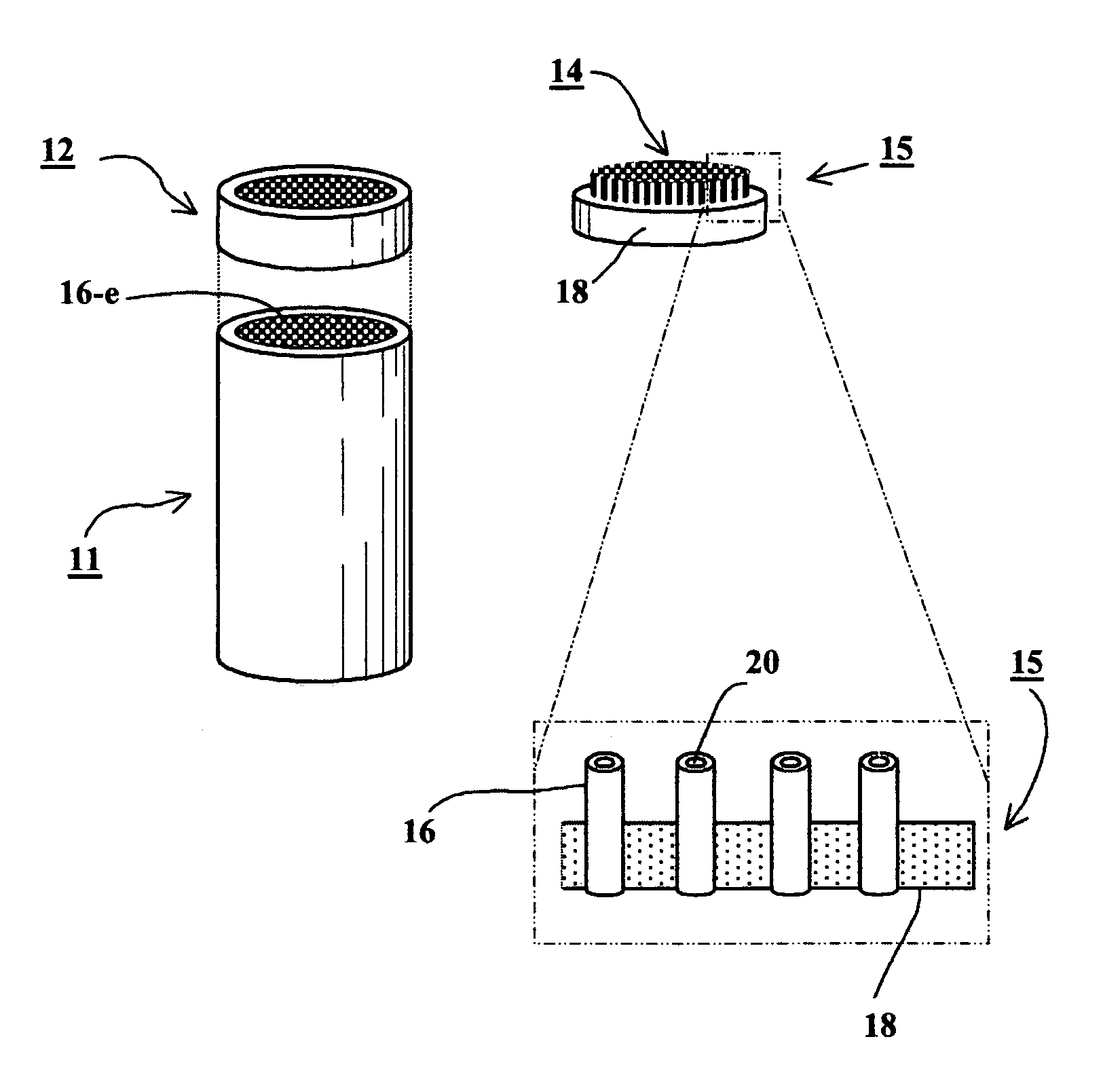
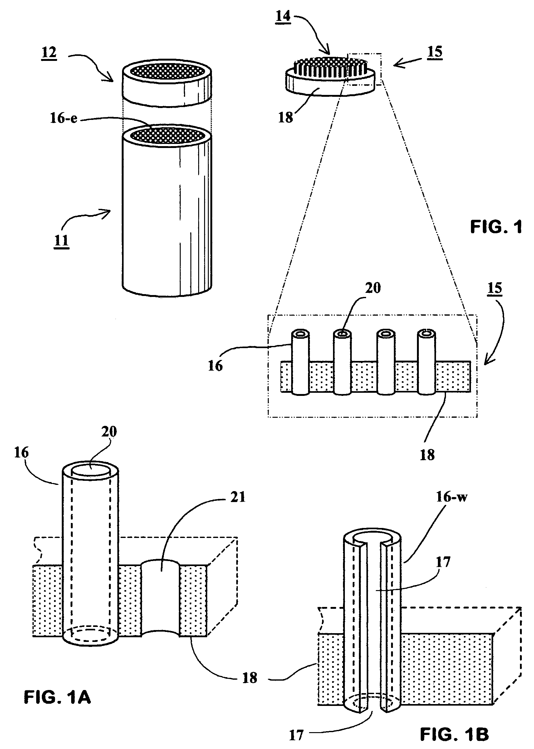
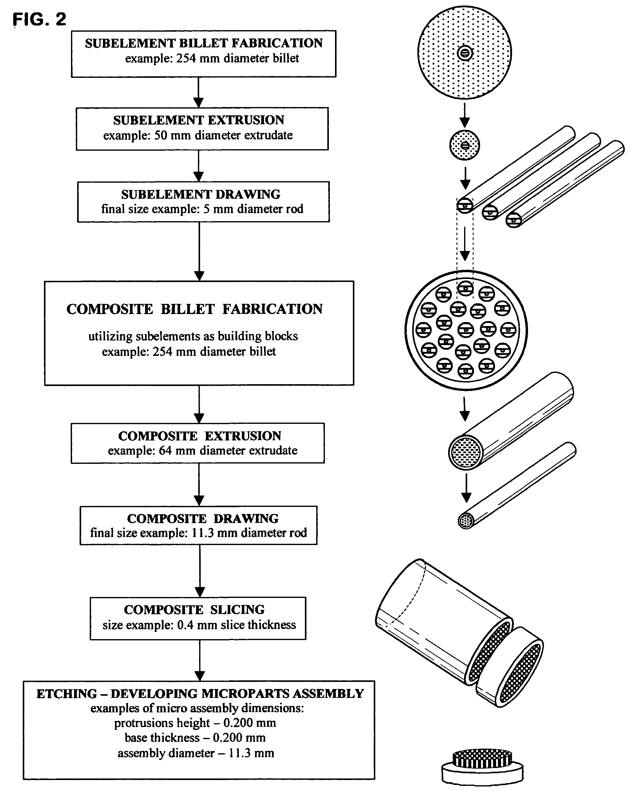
[0132]The invention is the method for manufacturing of microstructural components, microparts assemblies and individual microparts. More precisely method is for manufacturing a wafer or disk having an array of micro protrusions, protruding from and bonded to a substrate. Each protrusion constitutes an individual micropart, which could be solid or hollow, having simple or complex geometry, made of one or several materials.

[0133]The method comprising the steps of:[0134]1. Fabricating of unidirectional metal matrix composite having a structure, which define the microstructural assembly and microparts.[0135]2. Preparation of the composite slices or sections.[0136]3. Developing microparts assembly by partial etching of matrix, or developing individual microparts by etching a matrix entirely off. Developing the hollow microneedles by etching out the microneedles cores.

[0137]A microneedles wafer and an array of micropunches have a simple geometry and are convenient examples of microparts a...


PUM

PropertyMeasurementUnit
Lengthaaaaaaaaaa
Lengthaaaaaaaaaa
Lengthaaaaaaaaaa

Abstract

A method of fabricating microstructural components, microparts assemblies and microparts is disclosed. The method includes fabricating a unidirectional metal matrix composite made of materials selected to allow precise etching of different structural elements of the given composite without damage to each other. Cutting a composite to form slices or sections. Etching a matrix entirely out will produce wide assortment of microparts. Partial removal of matrix will form an array of microprotrusions protruding from a substrate. Etching out the microprotrusions cores will form hollow microprotrusions. The method of invention is suitable for fabricating of variety of microcomponents. For example: microneedles—a medical microdevice component having micron features, arrays of high strength micropins and micropunches, and precisely controlled unique microstructural surfaces.

Description

CROSS REFERENCE FOR RELATED APPLICATIONS[0001]This application is entitled to the benefit of Provisional Patent Application Ser. No. 60 / 425,998 filed Nov. 14, 2002.BACKGROUND[0002]1. Field of the Invention[0003]The present invention is a method of manufacturing microstructural components, microparts assemblies and microparts. More particularly, the invention is a method utilizing Metal Matrix Composites Technology and Low Temperature Superconductors Manufacturing Technology for microfabrication.[0004]2. Description of Prior Art[0005]In manufacturing, forming and removing of substantially homogenous materials are the two major or primary processes. The removing process creates a shape by destroying bonds among particles and removing material. Examples include mechanical turning, drilling and grinding, laser machining, electro discharge machining (EDM), chemical etching, traditional carving etc. The forming process creates a shape from a molten substance, solid particles and binder, e...

Claims


Application Information

Patent Timeline
IPC IPC(8): H01L21/00C23F1/00A61M37/00C23F1/04
CPCA61M37/0015C23F1/04A61M2037/003A61M2037/0038Y10T428/12465Y10T428/12486Y10T428/12431A61M2037/0053
Inventor OZERYANSKY, GENNADY
Owner OZERYANSKY GENNADY
Why Eureka
Try Eureka