
Parallel reactor for sampling and conducting in situ flow-through reactions and a method of using same

a parallel reactor and flow-through technology, applied in the field of apparatus and method for carrying out and in situ monitoring of the progress and properties of multiple parallel reactions, can solve the problems of slow and arduous chemical synthesis process, and achieve the effect of reducing the pressure in the reaction chamber

Inactive Publication Date: 2006-05-16
UNCHAINED LABS
View PDF48 Cites 32 Cited by
  • Summary
  • Abstract
  • Description
  • Claims
  • Application Information

AI Technical Summary

Benefits of technology

[0044]Another advantage of the present invention is the ability to interchange manifold assemblies coupled to the reactor assembly so as to create various flow paths and flow patterns through the reactor block. The interchangeable manifolds permit opposing sides of the reactor block to be set up having identical or different flow path configurations.
[0045]Other advantages of the present invention result from the use of small volume mixtures. In addition to conserving valuable reaction mixtures, decreasing sample size increases surface area relative to volume within individual reaction chambers. This improves the uniformity of reaction mixtures, aids gas-liquid exchange in multiphase reactions, and increases heat transfer between the samples and the respective reaction chambers. Because large samples respond much slower to changes in system conditions, the use of small samples, along with in situ monitoring and process control, also allows for time-dependent processing and characterization.Overview of Parallel Reactor
[0046]The parallel reactor system of the present invention is a modular platform for effecting combinatorial research in chemistry and materials science applications. Although the parallel reactor system of the present invention is designed to be a modular unit, the parallel reactor system can be designed for integration into a larger screening device as disclosed in commonly assigned U.S. application Ser. No. 09 / 548,848, the discussion of which is incorporated herein by reference.
[0047]The parallel reactor includes a plurality of reaction chambers that can be operated in parallel on a scale suitable for research applications, typically bench scale or smaller scale (e.g., mini-reactors and micro-reactors). The reaction chambers of the parallel reactor can typically, but not necessarily, be formed in, be integral with or be linked by a common substrate, be arranged in a common plane, preferably with spatial uniformity, and / or can share a common support structure or housing.
[0048]The same or different reactions (experiments) may be performed in each well. Thus, each reactor well may vary with regard to its contents during an experiment. Each reactor well can also vary by a process condition, including catalyst amounts (volume, moles or mass), ratios of starting components, time for reaction, reaction temperature, reaction pressure, rate of reactant addition to the reaction, reaction atmosphere, injection of a catalyst or reactant or other component (e.g., a reaction quencher) and other conditions that those of skill in the art will recognize. Each reaction chamber can also vary by the chemicals present, such as by using different reaction mixtures or catalysts in two or more reaction chambers.
[0049]The parallel reactor is also designed to permit separate agitation of each sample by stirring the reaction mixtures in the respective well at selected times during the experiment without depressurizing or lower the pressure of the reactor well. The parallel reactor also permits the injection of additional chemistry into a desired well at selected times during the experiment. Further still, the parallel reactor is designed to allow the real-time collection of samples under pressure from each well at any time during an experiment. Finally, the parallel reactor also permits the performance of flow-through reactions continuously or at selected times during the experiment.

Problems solved by technology

However, compared to HTS protocols, chemical synthesis has historically been a slow, arduous process.

Method used


Image

  • Parallel reactor for sampling and conducting in situ flow-through reactions and a method of using same
  • Parallel reactor for sampling and conducting in situ flow-through reactions and a method of using same
  • Parallel reactor for sampling and conducting in situ flow-through reactions and a method of using same

Examples


example 1

Liquid Phase Hydrogenation Reaction (High Pressure Sampling)

[0191]The parallel reactor 10 can be used for chemical reactions such as hydrogenation, oxidation, carbonylization and polymerization under pressure. The chemicals to be reacted can be in the form of a liquid, solid or slurry. The following example illustrates a typical use of the parallel reactor 10.

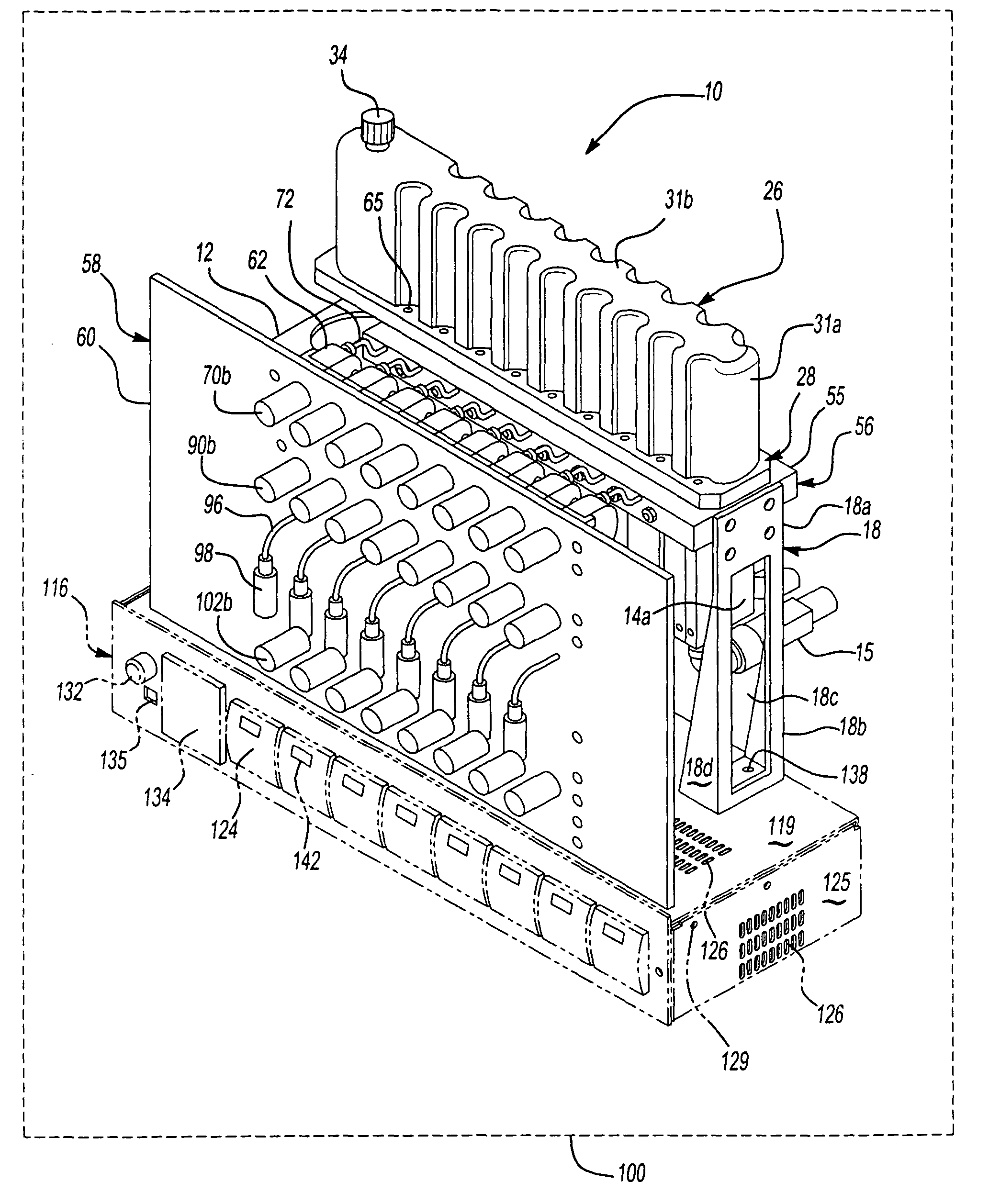
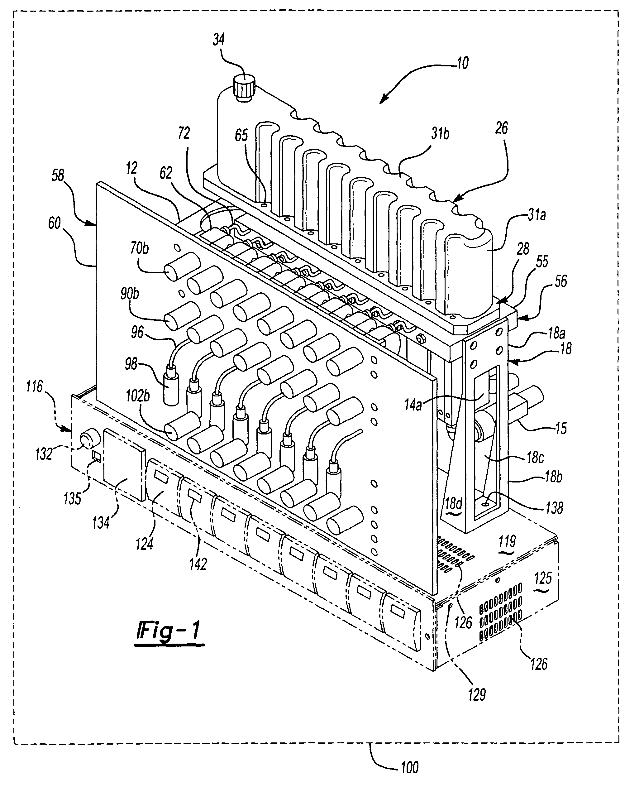
[0192]FIG. 1 illustrates the configuration of the parallel reactor system 10 that could be used for this example 1, with the following exceptions: the reactor system 10 could be assembled using the static pressure manifold bar 700 and the blank injection manifold 54.

[0193]To set up the experiment, clean each component comprising the reactor system 10 with tetrahydrofuran (THF) and replace O-ring seals and stirring blades 40. Attach the static pressure manifold 700 to the reactor block such that the flow path 21a is coupled to a common pressure source—Hydrogen gas. The remaining flow paths 20a, 20b and 21b are plugged. The stir ...

example 2

Method of Using Parallel Reactor 10

[0203]This illustrative example describes how the parallel reactor 10 can be used to screen, characterize or evaluate various material and thermal properties, including, but not limited to, molecular weight, specific gravity, elasticity, dielectric constant, conductivity or calorimetric data.

Reactor Block Assembly Set-up

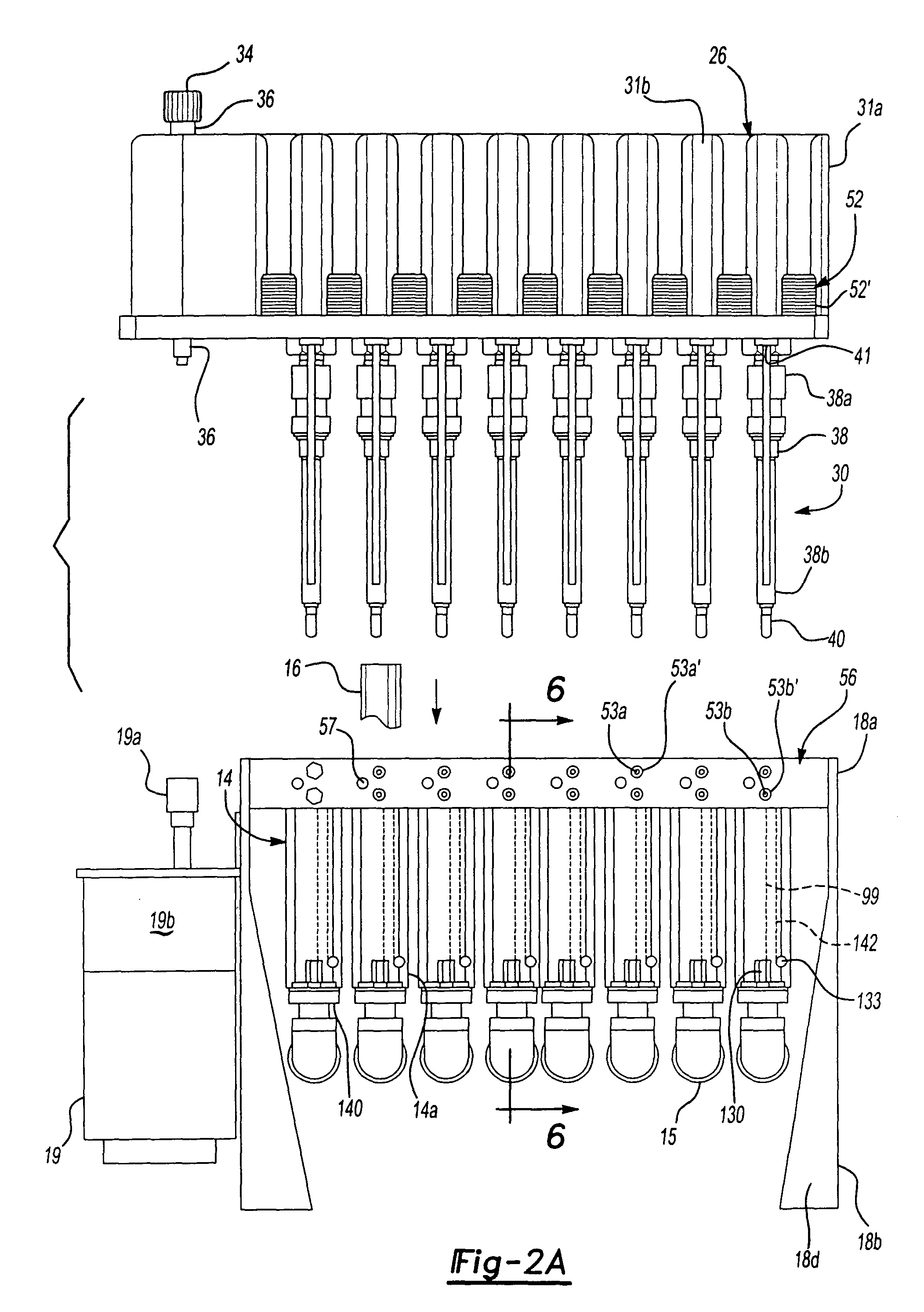
[0204]FIG. 1 illustrates an embodiment of a parallel reactor assembly that can be used to perform the following screening of various materials. The parallel reactor can include eight reactor wells, each well supporting a removable vessel that prevents direct contact of the reaction mixture with the well 14.

[0205]In this illustrative experiment, the reactor assembly also includes a stir top assembly supporting a stirring blade assembly for mixing the reaction mixtures, a pair of dip tubes and a blank injection manifold. The reactor assembly also includes a heater and motor control box assembly for controlling the temperature of each ...


PUM

PropertyMeasurementUnit
Pressureaaaaaaaaaa
Areaaaaaaaaaaa
Temperatureaaaaaaaaaa

Abstract

An apparatus for parallel processing of reaction mixtures, including a reactor block including reaction chambers for containing reaction mixtures under pressure, the reactor block further including a first sidewall, a second sidewall, and a first plurality of fluid flow paths providing fluid communication with the first sidewall and respective reaction chambers and the second sidewall and respective reaction chambers; a stirring system including a base plate defining a second plurality of flow paths, wherein respective flow paths of said second plurality of flow paths are in fluid communication with respective reaction chambers and respective fluid flow paths of said first plurality of flow paths, and the base plate also supports a plurality of stirring blade assemblies for mixing the reaction mixtures; interchangeable manifolds supported by the first sidewall and the second sidewall, the interchangeable manifolds defining a plurality of manifold inlet / outlet ports, wherein respective inlet / outlet ports of said plurality of inlet / outlet ports are in communication with respective fluid flow paths of said first plurality of fluid flow paths and permit fluid to be introduced into or vented from the respective reaction chambers; and a sampling manifold assembly coupled in fluid communication with the respective reaction chambers, wherein a portion of the reaction mixture retained in the respective reaction chambers can be withdrawn from the respective reaction chamber through respective fluid flow paths of said first plurality of fluid flow paths and respective flow paths of said second plurality of flow paths, or both, without depressurizing or lowering the pressure in the respective reaction chamber.

Description

[0001]The instant application is a division of U.S. patent application Ser. No. 09 / 826,606 filed Apr. 5, 2001 now U.S. Pat. No. 6,692,708.FIELD OF THE INVENTION[0002]The present invention relates to an apparatus and method for carrying out and in situ monitoring of the progress and properties of multiple parallel reactions.BACKGROUND OF THE INVENTION[0003]In combinatorial chemistry, a large number of candidate materials are created from a relatively small set of precursors and subsequently evaluated for suitability for a particular application. As currently practiced, combinatorial chemistry permits scientists to systematically explore the influence of structural variations in candidates by dramatically accelerating the rates at which they are created and evaluated. Compared to traditional discovery methods, combinatorial methods sharply reduce the costs associated with preparing and screening each candidate.[0004]Combinatorial chemistry has revolutionized the process of drug discov...

Claims


Application Information

Patent Timeline
IPC IPC(8): G01N33/00G01N31/00B01J19/00C40B60/14F28F27/00
CPCB01J19/0046F28F27/00Y10T436/11B01J2219/00283B01J2219/00308B01J2219/00351B01J2219/00477B01J2219/00481B01J2219/00495B01J2219/00585B01J2219/0059B01J2219/00698B01J2219/00718C40B60/14Y10T436/142222B01J2219/00155
Inventor CHANDLER, JR., WILLIAM H.
Owner UNCHAINED LABS
Learn More