

Method for manufacturing of an optical fiber with a decoupling interface for scattered light, use of an optical fiber and device for monitoring of the light power guided through an optical fiber
- Summary
- Abstract
- Description
- Claims
- Application Information
AI Technical Summary
Benefits of technology
Problems solved by technology
Method used
Image

Examples
first embodiment
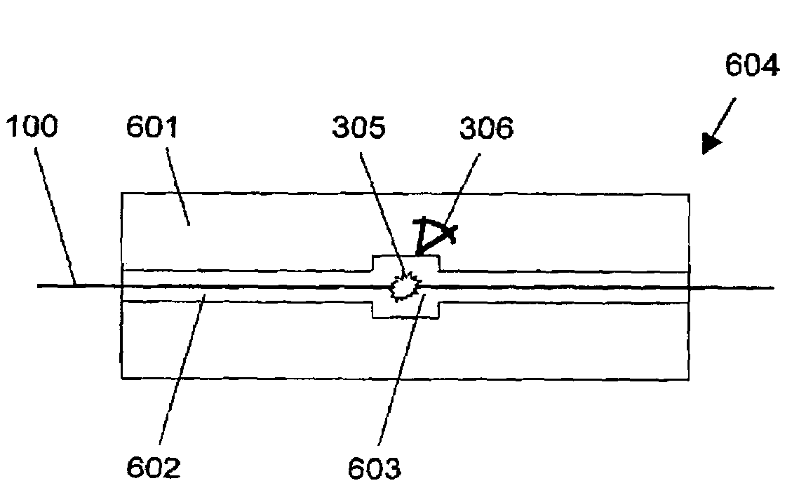
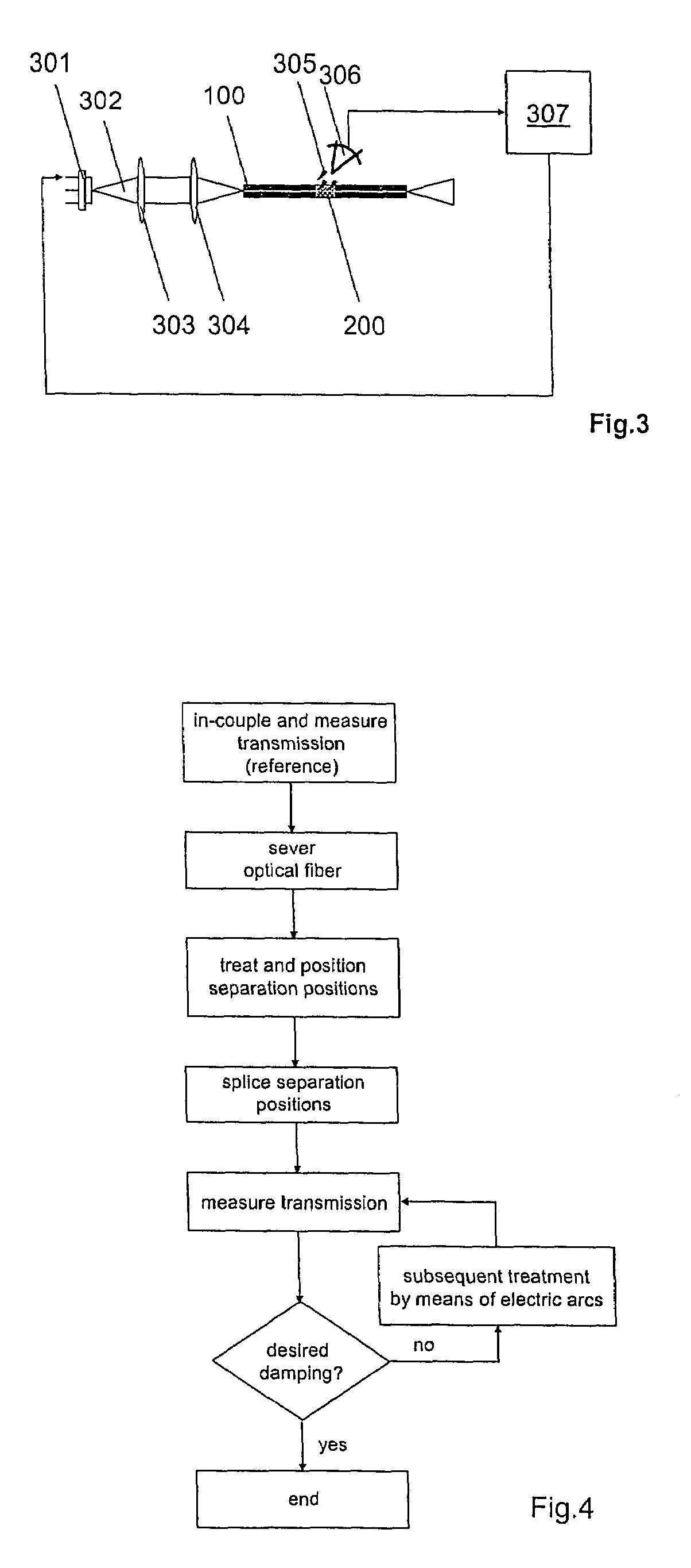
[0081]The decoupling interface 200 of the optical fiber 100 can be manufactured by different processes. One possible process according to the present invention is demonstrated in FIG. 4 as a flow chart. In this process, at first the light power of light source 301 transmitted through the optical fiber 100 is determined as a “reference measurement”. Thereafter, the optical fiber 100 is severed substantially perpendicular to the fiber axis, so that fiber pieces are formed.
[0082]The coating is removed from the resulting fiber pieces at their respective ends of the separation positions (so called “stripping”) and the ends are cleaned. The end surfaces of the fiber pieces are broken straightly and in a controlled way (so called “cleaving”). In a splicing device, the fiber pieces are then positioned along a straight line and thereafter directly spliced to each other at their front surfaces. Subsequently, the splicing position is modified in such a way, that a part of the guided light powe...
second embodiment
[0084]An alternative procedure for modifying an optical fiber according to the present invention is shown in FIG. 5 as a flow chart. Light is coupled into the fiber core at the fiber entry, and the transmitted light power is measured at the fiber end. The coating is removed from the optical fiber at the position to be treated, and the uncovered fiber cladding is cleaned. The fiber cladding is treated by means of electric arcs at the uncovered position while the optical fiber maintains straightly aligned, so that a partial mixture of the materials of the core and the cladding is obtained at this position, and as a result a part of the light is not guided through the optical fiber any longer, but emanates the optical fiber. The intensity of the scattered light can be adjusted by controlling the parameters of the electric arcs (e.g. duration, repetition frequency), in that the power transmitted through the optical fiber is monitored and the electric arc treatment is continued until a d...
PUM
| Property | Measurement | Unit |
|---|---|---|
| Particle diameter | aaaaa | aaaaa |
| Particle diameter | aaaaa | aaaaa |
| Particle diameter | aaaaa | aaaaa |
Abstract
Description
Claims
Application Information