Polymer electrolyte fuel cell

Inactive Publication Date: 2006-06-13
PANASONIC CORP
View PDF7 Cites 14 Cited by
  • Summary
  • Abstract
  • Description
  • Claims
  • Application Information

AI Technical Summary

Benefits of technology

[0021]The present invention is such one as having been conceived in view of above described problems of prior art, and the object of the present invention is to provide a polymer electrolyte fuel cell having an improved basic pe

Problems solved by technology

Accordingly, if the supplied water vapor and the water generated by the electrode reaction are not quickly exhausted to outside, the gas diffusion electrodes or the gas diffusion layers suffer from water undesirably retained therein and get worse in the gas diffusion property, whereby the cell characteristics gets deteriorated.
However, such conventional countermeasures are not enough.
Therefore, when e.g. discharging currents vary, or when flow rates or amounts of humidification of the supplied gases change, then either amounts of water in the catalyst layers become short, or excessive water blocks the supplied gases from reaching the polymer electrolyte membranes, thereby to deteriorate resultant cell characteristics.
Such technology cannot solve the problem regarding the water exhaustion property in the thickness direction of the gas diffusion layer.
Furthermore, it is difficult and is a factor of cost increase to manufacture a carbon cloth having a mesh varying its fineness or coarseness thereof gradually in the surface plane direction thereof.
This is likely to cause the amount of water at the outlet side to exceed a given threshold level, thereby to bring the outlet side to an excessively wet condition.
For this reason, the fuel cell is likely to have a deteriorated wat

Method used


Image

  • Polymer electrolyte fuel cell
  • Polymer electrolyte fuel cell
  • Polymer electrolyte fuel cell

Examples


Example

Example I-1

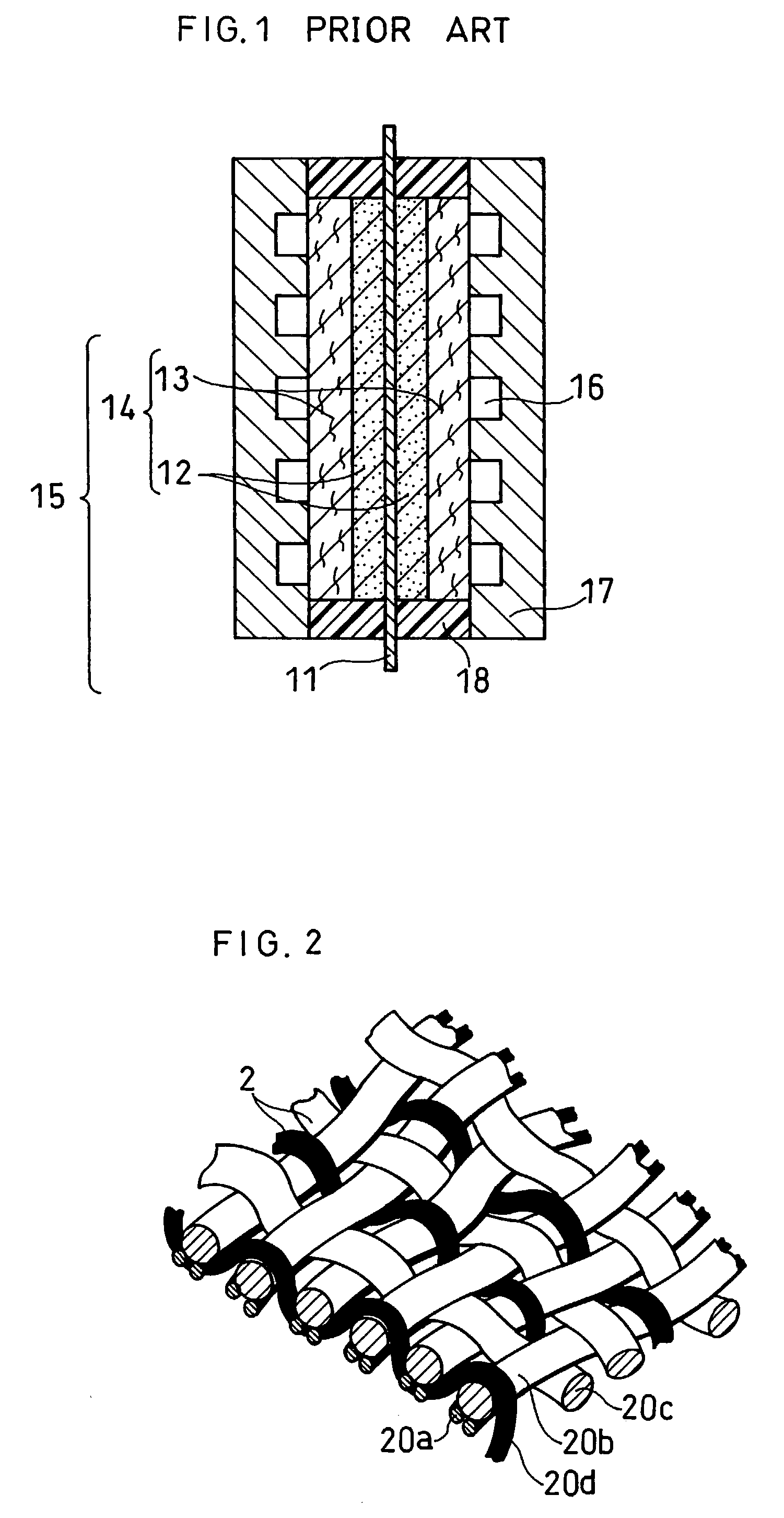
[0082]Firstly, as schematically shown in FIG. 2, a carbon cloth, having a finer mesh at the catalyst layer side thereof and a coarser mesh at the separator plate side thereof, was made as follows.

[0083]Threads each having a diameter of about 300 μm and made by stranding up PAN fibers having a diameter of about 10 μm was prepared as wefts 20a for a first layer. Likewise, threads each having a diameter of about 600 μm and made by stranding up PAN fibers having a diameter of about 10 μm was prepared as wefts 20b for a second layer. The threads having a diameter of about 600 μm were further used as warps 20c in the second layer to knit the wefts 20b of the second layer. Further, the threads having a diameter of about 300 μm were used as warps 20d to knit the wefts 20a, 20b of both the first layer and the second layer. Thereby, a cloth or precursor of carbon cloth 20 was made.

[0084]The thus made precursor of carbon cloth was heated to be graphitized at 2,000° C. in a nitrogen ...

Example

Example I-2

[0095]A multi-layer carbon cloth 50 as schematically shown in FIG. 5 was made as follows. A first cloth was made by plain weave, using threads having a diameter of about 300 μm and having been made by stranding up PAN fibers having a diameter of about 10 μm. A second cloth was likewise made by plain weave, using threads having a diameter of about 600 μm and having been made by stranding up PAN fibers having a diameter of about 10 μm. The first cloth and the second cloth were then heated at 2,000° C. in a nitrogen atmosphere for 24 hours to get graphitized to be carbon cloths.

[0096]These carbon cloths were subjected to water repellent treatment in a manner similar to that described in EXAMPLE I-1, and the carbon cloth 50a made of the first cloth was stacked on the carbon cloth 50b made of the second cloth to be the multi-layer carbon cloth 50. FIG. 5 is an oblique view, partially in cross-section, of such multi-layer carbon cloth 50 seen from the second cloth side, schemat...

Example

Example I-3

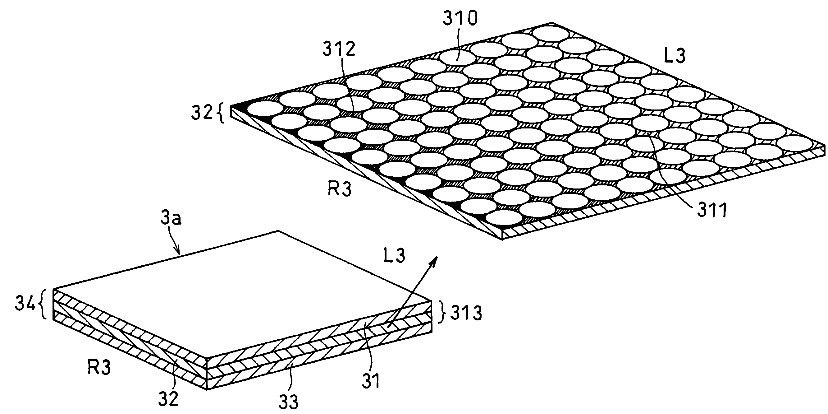
[0098]A single layer carbon cloth 60 as schematically shown in FIG. 6 was made as follows. A cloth was made by plain weave, using threads having a diameter of about 300 μm and having been made by stranding up PAN fibers having a diameter of about 10 μm, and also using threads having a diameter of about 600 μm and having been made by stranding up PAN fibers having a diameter of about 10 μm. More specifically, each 600 μm thread was placed for every consecutive three 300 μm threads for both the wefts and the warps, so that each 600 μm thread was placed between neighboring two groups of three consecutive threads as to both the weft arrangement and the warp arrangement as can be understood from FIG. 6. The thus made cloth was then heated at 2,000° C. in a nitrogen atmosphere for 24 hours to get graphitized to be the carbon cloth 60.

[0099]FIG. 6 is an oblique view, partially in cross-section, of such carbon cloth 60, schematically showing its structure. The thus made carbon cl...


PUM


Abstract

A porous supporting carbon body of a gas diffusion layer is provided with a larger number of smaller pores at its catalyst layer side and a smaller number of larger pores at the other side, particularly with an appropriate distribution of finer mesh at its catalyst layer side and coarser mesh at the other side. As a result, a high performance polymer electrolyte fuel cell is obtained in which water generated at the catalyst layer is quickly sucked out to the gas diffusion layer, and is evaporated at the gas diffusion layer to be effectively exhausted to outside the fuel cell, so that excessive water can be prevented from retaining in the gas diffusion electrode, with the polymer electrolyte membrane being maintained at an appropriately wet condition.

Description

BACKGROUND OF THE INVENTION[0001]The present invention relates to a polymer electrolyte fuel cell to be used for co-generation systems and mobile electric power generators for e.g. automobiles or the like, particularly to a gas diffusion layer to be used for such fuel cells.[0002]In a polymer electrolyte fuel cell, a fuel gas such as hydrogen and an oxidant gas such as air are supplied to a pair of gas diffusion electrodes (anode for the fuel gas and cathode for the oxidant gas), and are electrochemically reacted with each other at catalyst layers of e.g. platinum therein. Such reaction generates electricity and heat at the same time. A general structure of such polymer electrolyte fuel cell is shown in FIG. 1.[0003]Referring to FIG. 1, opposite main surfaces of a polymer electrolyte membrane 11 for selective transporting hydrogen ions are provided with a pair of catalyst layers 12 to intimately contact the membrane respectively. Each catalyst layer 12 has a carbon powder as a main ...

Claims


Application Information

Patent Timeline
IPC IPC(8): H01M4/86H01M4/90H01M4/96H01M4/88H01M4/92H01M8/04H01M8/10
CPCH01M4/8605H01M4/8821H01M4/92H01M4/96H01M8/04089H01M8/1004H01M4/8828H01M4/8642H01M4/8652H01M4/8657Y02E60/521Y02E60/50H01M4/86
Inventor YOSHIDA, AKIHIKOYAMAMOTO, MASAONIIKURA, JUNJITAKEBE, YASUOSAKAI, OSAMUUCHIDA, MAKOTO
Owner PANASONIC CORP
Why Eureka
Try Eureka