Disk, method for making it free of asperities utilizing a step of exposing a surface of the disk to a gas cluster ion beam and disk drive unit for using the disk

a technology of asperity and disk, applied in the field of magnetic disk, can solve the problems of reducing the recording density, reducing the distance, and the risk of a so-called “head crash” and other problems, to achieve the effect of reducing surface roughness, reducing manufacturing costs, and less costly

Inactive Publication Date: 2006-06-20
WESTERN DIGITAL TECH INC
View PDF11 Cites 13 Cited by
  • Summary
  • Abstract
  • Description
  • Claims
  • Application Information

AI Technical Summary

Benefits of technology

[0022]A substantial advantage of the method of the present invention is that chemical mechanical polishing of the substrate, base-coated substrate, or wafer is not needed. It is expected that this will significantly reduce manufacturing costs associated with fabrication of a high-density magnetic disk; chemical mechanical polishing will become unnecessary, as will removing remnants of the polishing slurry used during chemical mechanical polishing and otherwise cleaning the substrate, and disposing of the used slurry. The gas cluster ion beam technique for smoothing is capable of reducing surface roughness on an atomic scale, and removing any asperities that would be large enough to be detrimental to the performance of a disk drive unit.
[0023]The use of a base coating such as glassy carbon or amorphous carbon submerges asperities on the substrate. It is anticipated that smoothing the base coating with the aid of gas cluster ion beam processing will be more rapid, and less costly, than it would have been if gas cluster ion beam processing had been used to remove asperities from the substrate itself, without the presence of a base coating.

Problems solved by technology

However, the risk of a so-called “head crash,” when a head actually touches the surface of a magnetic coating or possibly gouges into it, usually caused by the presence of asperities, also increases as the flying distance decreases.
The reason is that a wavy surface or a rough surface that creates turbulence would make it necessary to either increase the flying distance, and thus reduce the recording density, or to increase the risk of a head crash and thus increase the prospect of losing data or physically damaging the disk drive unit.
It has been found that aluminum substrates are limited in how smooth their surfaces can be made.
One drawback of CMP is that the used slurry, with its abrasive particles and glass residue, is relatively expensive to dispose of in an environmentally responsible manner.
Additionally, cleaning the polished substrates is relatively costly since every last bit of abrasive grit and glass residue must be removed.

Method used


Image

  • Disk, method for making it free of asperities utilizing a step of exposing a surface of the disk to a gas cluster ion beam and disk drive unit for using the disk
  • Disk, method for making it free of asperities utilizing a step of exposing a surface of the disk to a gas cluster ion beam and disk drive unit for using the disk
  • Disk, method for making it free of asperities utilizing a step of exposing a surface of the disk to a gas cluster ion beam and disk drive unit for using the disk

Examples


first embodiment

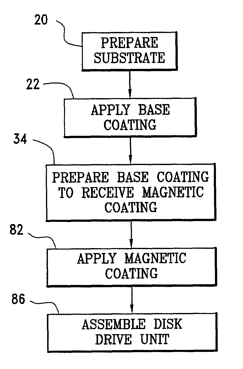
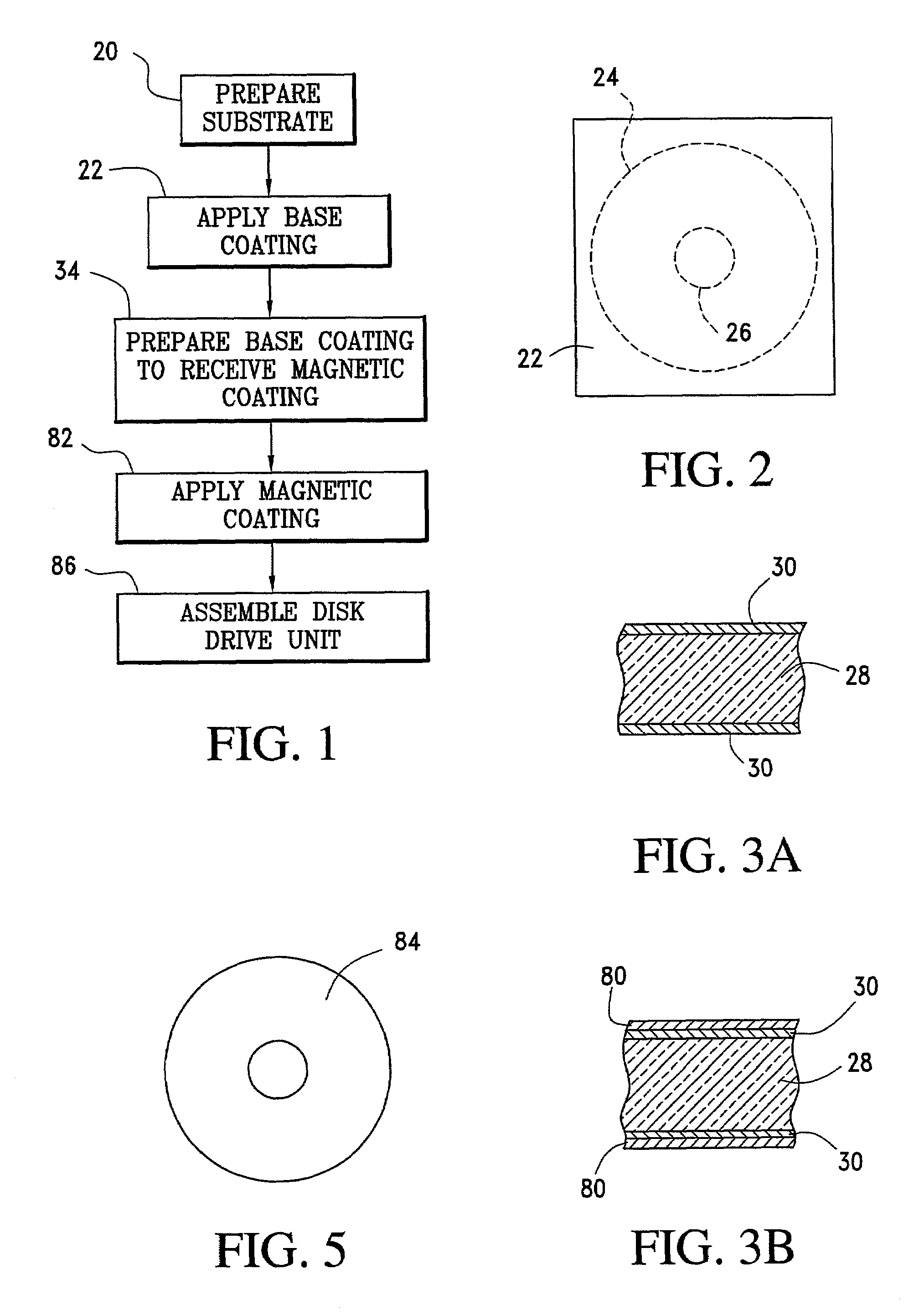
[0039]A first embodiment of a process for fabricating a magnetic disk, and a disk drive unit having one or more such disks, is illustrated in FIG. 1. A substrate is prepared in step 20. The substrate is preferably made of a sheet of commercially available glass about one millimeter thick. Suitable sheets of high quality glass that are made by what is known as the fusion process and that have smooth, flat surfaces can be obtained from Corning Incorporated (of One Riverfront Plaza, Corning, N.Y. 14831, USA) under purchasing code 1737. The surfaces of the sheets are protected by thin plastic film until ready for use.

[0040]A number of substrates can be fabricated simultaneously by stacking such film-protected sheets of glass and fabricating them simultaneously. FIG. 2 illustrates the uppermost sheet 22 of a stack. The sheets are cut along dotted line 24 to provide an outer diameter of 95 millimeters and along dotted line 26 to provide a central opening with a diameter of 25 millimeters....

second embodiment

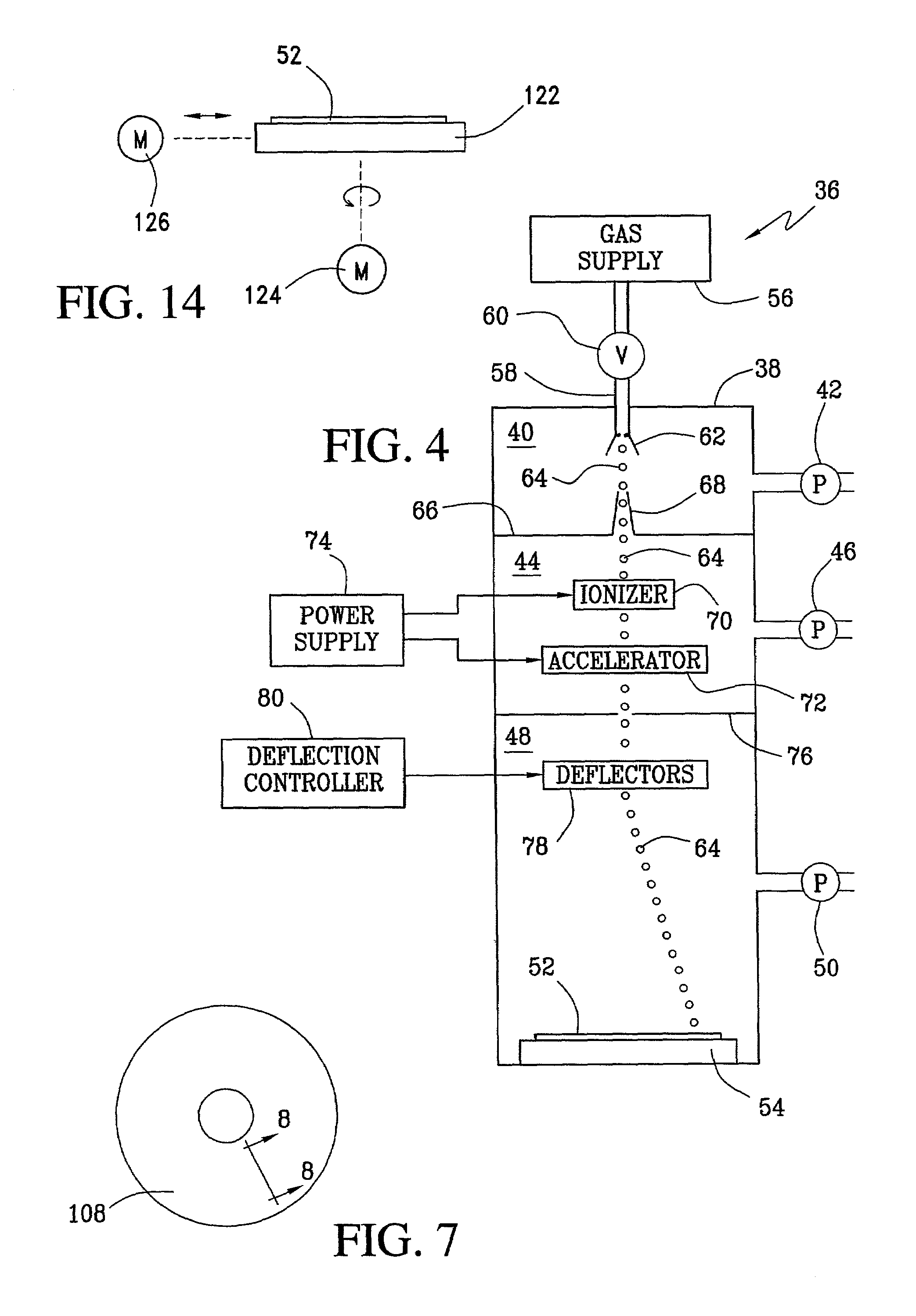
[0056]A magnetic disk 108 made in accordance with a second embodiment of the process of the present invention is illustrated in FIG. 7. Like the disk 84 in FIG. 5, the disk 108 in FIG. 9 includes a substrate, a base coating (such as glassy carbon or amorphous carbon, although metal or a metal alloy may be used) on the top side and the bottom side of the substrate, and a magnetic coating on the top base coating and the bottom base coating. Unlike the disk 84 of FIG. 5, however, the base coating on the top and bottom sides of the substrate for magnetic disk 108 is textured. The texture is such that concentric, annular valleys are carved out of the base coating at spaced-apart positions, leaving thin, annular, concentric plateaus between the valleys. When the magnetic coating is applied, the presence of these plateaus helps align the magnetic moments of the magnetic domains in a tangential direction. This enhances the magnetic properties of the magnetic coating. Furthermore, it is anti...


PUM

PropertyMeasurementUnit
thickaaaaaaaaaa
diameteraaaaaaaaaa
diameteraaaaaaaaaa

Abstract

A method for making a magnetic disk, without chemical mechanical polishing to remove asperities, includes the steps of placing an annular-shaped element in a vacuum chamber, exposing a surface of the element to a beam of gas clusters while it is in the vacuum chamber, and thereafter applying a magnetic coating. The annular-shaped element may be a substrate, or it may be a substrate with a base coating such as glassy carbon or amorphous carbon. The substrate may be made of glass, preferably high quality fusion glass. The surface of the annular element may be textured by forming a sequence of concentric annular valleys, with plateaus being left between the valleys, before the magnetic coating is applied. A semiconductor wafer may also be smoothed by a beam of gas clusters to prepare the wafer for photolithography.

Description

BACKGROUND OF THE INVENTION[0001]1. Field of the Invention[0002]The invention relates to a disk, particularly a magnetic disk, to a method for making the disk, and to a disk drive unit with one or more such disks.[0003]2. Background Information[0004]An annular-shaped substrate that carries a magnetic coating on one or both sides is commonly called a magnetic disk. Magnetic disks are typically used in disk drive units in computers, for example, for data storage applications. The substrate of a magnetic disk may be formed from aluminum or from glass, for example, and the magnetic coating carried by the substrate may be deposited not on the substrate's surface itself, but on a base coating interposed between the substrate and the magnetic coating. It is known to use glassy carbon, amorphous carbon, or a metal or metal alloy for such a base coating. The magnetic coating may be a multi-layer coating. A typical example would be a seed layer, followed by a chrome layer, followed by a cobal...

Claims


Application Information

Patent Timeline
Patent Type & Authority Patents(United States)
IPC IPC(8): G11B5/82G11B5/84
CPCG11B5/8404G11B5/82
Inventor ERICKSON, KARL ROBERTKUCHTA, DOUGLAS ALLANPILTINGSRUD, DOUGLAS HOWARD
Owner WESTERN DIGITAL TECH INC
Why Eureka
Try Eureka