Turbine, particularly useful for small aircraft

a turbo engine and small aircraft technology, applied in the field of turbo engines, can solve the problems of gear alignment tolerances, insufficient lubrication, and increasing mechanical stress on moving parts, so as to improve the efficiency of the turbo engine, reduce mechanical stress, and reduce wear in moving parts

Active Publication Date: 2006-06-27
FLORESTAN TECH PTY LTD
View PDF20 Cites 23 Cited by
  • Summary
  • Abstract
  • Description
  • Claims
  • Application Information

AI Technical Summary

Benefits of technology

[0034]The turbo-engine design of the present invention retains some of the general aspects found in Argentine patent application serial number P010105645, but overcomes technical problems mentioned hereinabove by means of an overall arrangement that puts emphasis on simplicity and on a series of innovative systems. These include: an internal oil system, a power-regulated and starting control system, an advanced combustion chamber with flame front stability control and a gearbox coupling systems to the high-speed shaft, to the power output shaft and to the oil pump. These systems drastically reduce wear in the moving parts thereby improving efficiency of the turbo-engine and do away with the need of complex heat removal systems together with a decrease of mechanical stress on high-speed components subjected to load transients, without requiring additional components, increasing durability and reliability with minimum maintenance and reducing weight and the quantity of necessary parts.
[0035]The present invention consists of a compact turbo-engine providing better performance, greater durability and lower maintenance for delivering mechanical work on a shaft and thrust by means of exhaust gases and / or heat, with powers below 600 HP in its preferred embodiment. This turbo-engine comprises an air compression stage, an advanced annular combustion chamber providing flame conduction and flame front stability control by means of jets generating vortices in the cold region, a high-speed, cantilevered shaft to which the compression and expansion stages are integrated, supported by a pair of bearings placed in the “cold” side, wherein the high-speed bearings are lubricated by an efficient oil distribution and direction system, the compact gearbox using substantially planar gear-wheels, a starter control system, an electrical power-regulation and redundant electrical fuel injection system for power regulation and easily assembling systems between the gearbox and the compressor turbine subsystems by means of extractible splines conveying smooth transmission and reduced wear of the parts.

Problems solved by technology

One of the greater technical problems in designing an efficient, low-power turbine is related to the fact that, due to physical operational principles, a reduction in the flow capacity and size thereof leads to having to increase the rotation speed of the compressor-turbine assembly, thereby significantly increasing mechanical stress on the moving parts materials.
This conditions the life-term of the components and is in part associated with the wear of the moving parts.
The main causes of wear tend to be inadequate lubrication of the bearings turning at high speed, gear alignment tolerances and imbalance, stress resulting from thermal expansion of materials and transmission of vibrations between the high-speed shaft, the step-down gears and the output shaft delivering useful work, be it in electrical generators, propellers, water pumps, compressors et cetera.
The usefulness of this solution is nearly exclusively limited to lightweight shafts turning at very high speeds.
These weight and speed limitations restrict the power range.
Magnetic bearings are extremely expensive and complex and, hence, not cost-effective in turbo machines of powers under 1,000 HP.
In order to achieve a low-maintenance turbine, the problems leading to wear in the moving parts need to be addressed since they shorten the useful lifespan of the mechanical parts and increase the frequency of having to change the oil and filters.
Friction between the moving parts of the bearings leads to less efficiency since mechanical energy is converted into heat, leading to heating of the oil.
This poses an additional requirement of having to provide means (radiators) for removing heat and distribution ducts for the oil systems, thereby increasing the quantity of components and complexity, in detriment of overall weight and compactness.
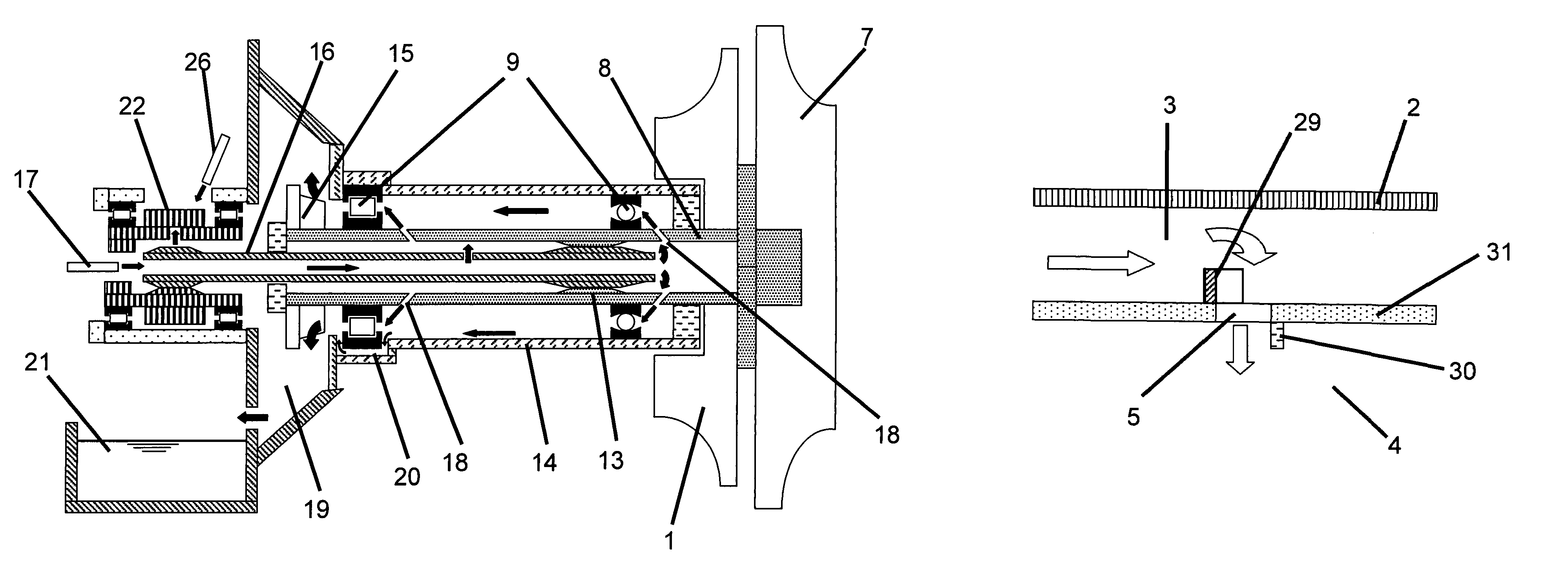
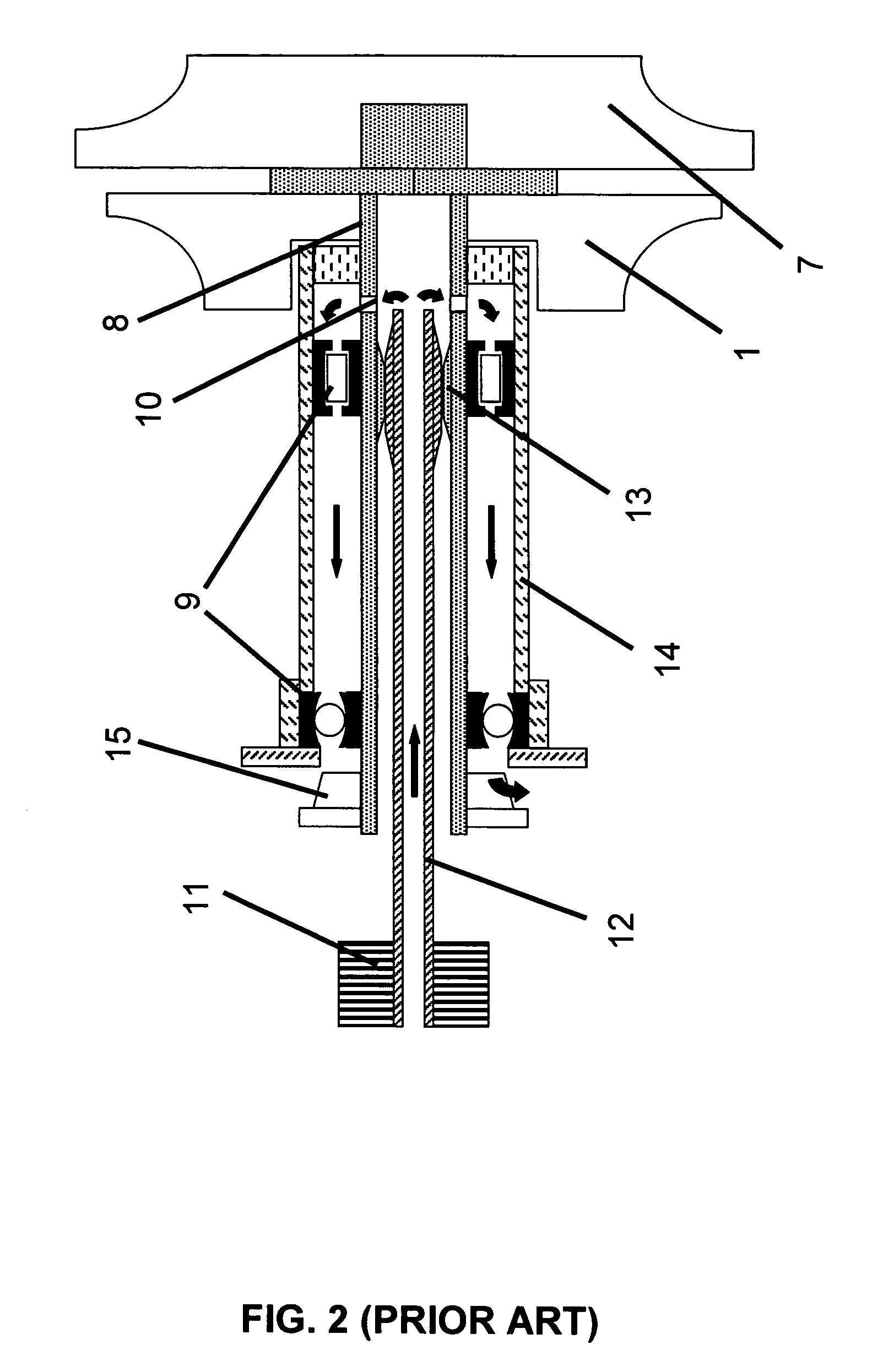
However, they are scarcely efficient at wetting the roller paths due to the impact and dispersion of the oil jets against the balls moving at speeds, as a result of the substantial speed difference between the jets and the balls.
Although this system lessens the impact of the abovementioned effects, it fails to solve the drawbacks conditioning the useful lifespan of the bearings.
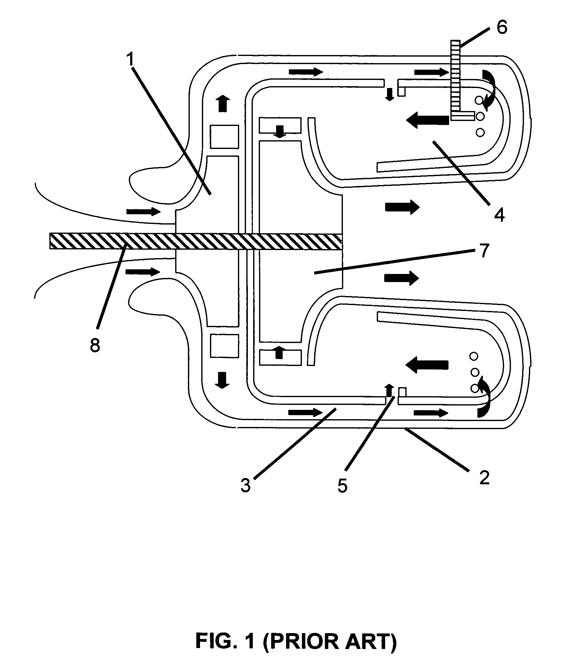
One of the main drawbacks of this arrangement is the transmission of vibrations towards the high-speed shaft, which is detrimental to the useful lifespan of the bearings and is exacerbated by the interaction of more than one torque transmission point.
Another factor limiting the lifespan of the turbine is the maximum temperature to which the region at the edge of the turbine rotor vane 7 is subjected, this being the part most prone to stresses and temperatures.
The problem of confining the flame front to the hot region furthermore causes emission of contaminants as a product of incomplete combustion and problems of sudden flame quenching during acceleration and deceleration transients.
An attempt to avoid this uses a flame arrester in the primary, up-current from the turbine 7 intake, with the consequential addition of a device that requires high-temperature resistant materials, meaning more parts and loss of pressure, adversely affecting weight, simplicity, durability and efficiency of the turbo-engine.
Hence a drawback is the need for an additional coupling gear, resulting in more parts, weight, difficult disassembling and detrimental to compactness and simplicity.
These devices have to be adjusted with extreme precision because of the narrow tolerances they are built around and are intensely affected by variations of atmospheric conditions.
Since these mechanisms are made up of a number of parts, it is considerably expensive and difficult to include redundant systems to improve the reliability thereof and of the entire engine turbine in general.
Furthermore, the operation of these mechanisms involves a complex ignition and control procedure during which the different ignition stages have to be manually enabled and disabled, opening the door to a new range of potential faults arising from human operational errors.
Although this reduces the probability of human error, yet more systems are added to the already extremely complex systems of the turbine per se, adding further penalties in terms of cost and weight and introducing new fault sequences.
Because the auxiliary systems of the turbo-engines are complex, the power consumed by the auxiliary systems of high-power turbo-engines is similar to that of the systems of small turbo-engines.
This curtails the design and implementation of low-power turbo-engines, as upper limits in the power consumption of auxiliary systems come into play in order for the operation of the turbine at low-power cruising speeds be self-sustainable.
This prior art has the drawback that the control valve has to be operated via servomechanisms or else by means of the usual control cables, adding more devices with their attendant fault and maintenance rates.
In conclusion, it can be said that the traditional aircraft turboshaft designs cannot be extrapolated down to the low-power range and still match the reliability, durability, efficiency and simplicity required in commercial aviation or avoid drawbacks in maintenance and wear for the generation of electricity or useful work on the ground.
This is due to the complexity and technical problems that need to be overcome go up as the power and the size thereof go down.
Proof of this is that available low-power turboshafts used for fixed or military installations are very complex, have limited lifespan, require a lot of maintenance and are pretty expensive considering the low power levels involved.

Method used


Image

  • Turbine, particularly useful for small aircraft
  • Turbine, particularly useful for small aircraft
  • Turbine, particularly useful for small aircraft

Examples


Embodiment Construction

[0042]I have found that the turbo-engine of the present invention is able to operate at speeds up to 70,000 RPM on the high-speed shaft, with an extended life-term of the high-speed shaft bearings by means of an oiling system such as schematically shown in FIG. 3. The physical arrangement of the annular combustion chamber, compressor and turbine together with the arrangement of a pair of bearings in the cold region of the cantilever compressor-turbine assembly allows the oil operation conditions on the bearings to be relaxed.

[0043]The engine is assembled with a hollow high-speed shaft 8 on one end of which the compressor 1 and the turbine 7 are mounted to be supported on a pair of bearings 9. The bearings 9 are externally anchored by means of a jacket 14 and house a removable hollow spline 16 inside. Oil 17 enters through one end of the spline and is injected through orifices 18 into the shaft 8 where it is directed towards the ball-roller-paths of the bearings.

[0044]The oil is urge...


PUM


Abstract

A turbine includes a combustion chamber with deflectors generating vortices in a secondary gas flow into the combustion chamber, thereby confining the flame front from penetrating into the cold region of the chamber under variable operating conditions, simplifying cooling of the chamber walls. The turbine further includes devices for decoupling vibrations between the high- and low-speed shafts, including a loosely mounted spline coupling the high-speed shaft to the step-down system and disk dampening means coupling the step-down system to the low-speed output shaft.

Description

FIELD OF THE INVENTION[0001]The present invention is related to a compact, lightweight, efficient and durable turbo-engine able to deliver power to a shaft as well as thrust from the reaction of the exhaust gases and heat. One practical application of the present turbo-engine is for generating electricity. Another application is an engine for propeller-driven aircrafts whether airplanes or helicopters, in marine uses for driving an underwater propeller, or any other application requiring delivery of power to a rotary shaft, whereby the balance of energy of the exhaust gases may be used for cogeneration or directly as heat.BACKGROUND OF THE INVENTION[0002]To be cost efficient, terrestrial electrical generators under 1,000 HP use reciprocating engines as their power source. Reciprocating engines use up a lot of closed space which has to be adapted to tolerate heavy weights and medium- and low-frequency vibrations, high maintenance costs and a narrow range of fuels. Furthermore, these ...

Claims


Application Information

Patent Timeline
Patent Type & Authority Patents(United States)
IPC IPC(8): F02C3/22F01M1/00F01D25/18F02C7/06F02G1/055F04D27/00F16D3/06F02C1/00F04D29/08F01D19/00F01D25/04F01D25/16F02C7/00F02C7/20F02C7/36F02C9/28F04D29/00F23R3/20F23R3/52F23R3/58
CPCF01D25/18F02C7/06Y10T74/19456Y02T50/671Y02E20/14F16C19/54F16C33/6677F16C2360/23Y02T50/60
Inventor LABALA, GUSTAVO FRANCISCO
Owner FLORESTAN TECH PTY LTD
Why Eureka
Try Eureka