[0030]The technical paradox concerning, on the one hand, acceptance of the enrichment with inert ingredients in the loop of the high-pressure
synthesis system and, on the other, the increased costs for providing secondary compression does no longer exist in this case when the whole recycle gas
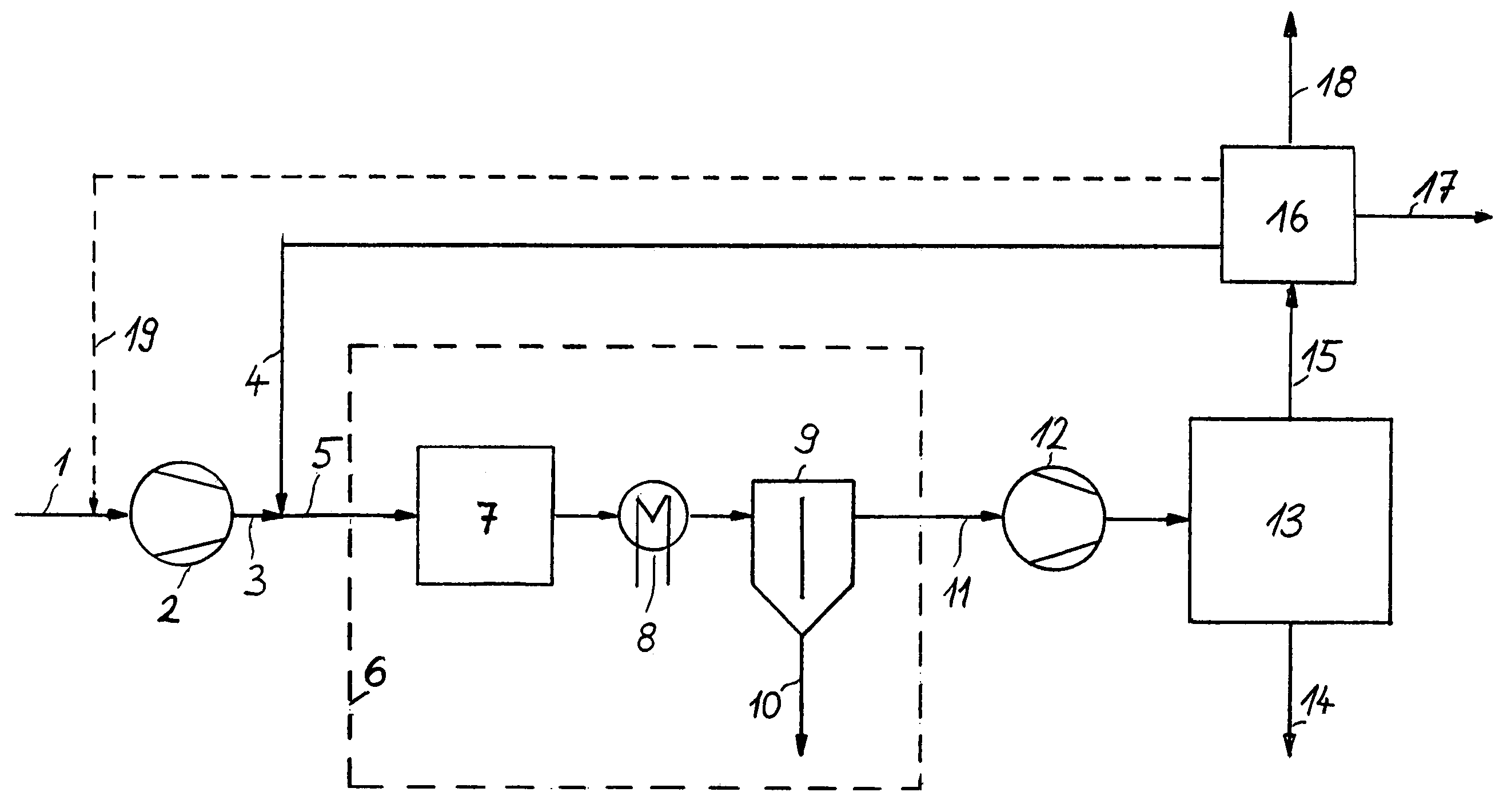
stream 4 recovered from the purge gas in
recovery unit 16 can be returned to a synthesis
system operating at a lower pressure, hence without the necessity of providing a secondary compression, which constitutes an
advantage of the invention. It is therefore no problem to reduce more efficiently the enrichment with inert ingredients in the loop system.
[0031]When comparing a conventional high-pressure ammonia synthesis with a high-pressure synthesis system of the same capacity and designed according to this invention, it becomes obvious that the high-pressure synthesis system described in this invention permits a substantially higher efficiency when operated at the same synthesis pressure, since the lower concentration of inert ingredients significantly reduces the required catalyst volumes, increases the
partial pressure of the ammonia at the reactor outlet and consequently also shifts the ammonia
dew point, reduces the amount of
refrigerant required to condense the ammonia produced and finally, as a result of the smaller overall volume of recycle gas, diminishes the expenditure necessary to sustain the recycle gas loop, the said features constituting advantages of this invention.
[0032]A comparison of conventional low-pressure ammonia synthesis systems with the low-pressure ammonia synthesis system designed according to the invention reveals the
advantage of this invention that the thermodynamic
reaction conditions are more favourable since the concentration of inert ingredients in this case is also very low due to the make-up gas
processing, and even if several make-up gas systems are lined up, the content of inert ingredients only rises slightly from one system to the next. Hence, these sections of the
plant also require smaller catalyst volumes, or alternatively, a ratio of highly active to standard catalysts that is lower than hitherto needed, which constitutes an
advantage of the invention. It is, for example, possible to improve the efficiency by using smaller amounts of highly active, enhanced
magnetite catalysts with promoters for low pressure as well as
noble metal catalysts such as those based on
ruthenium. This also includes nitrides of sub-group numbers VI and VIII in the
periodic table of the elements.
[0033]A further advantage of the invention consists in the possibility of providing very large
plant capacities using conventional sizes of equipment and splitting the production between several synthesis systems, so that there is no need to accept the detriments which normally occur when switching from a single-
train to a multiple-train concept. The components of a conventional high-pressure ammonia synthesis
plant, which are critical to the size, are as a rule the synthesis
gas compressor and the hot apparatus for the high-pressure synthesis loop. These systems are to some extent subjected to lower loads in configurations according to this invention, since the second stage of the synthesis
gas compressor must only perform a secondary compression of a certain part of the
total synthesis gas volume, i.e. the part not converted into product and not condensed in the low-
pressure system. Furthermore, the lower content of inert ingredients in the high-pressure synthesis loop produces the effect that the high-pressure synthesis loop can be smaller in size for the same production output as that of a plant with just one
reaction system. Instead of building a smaller plant right from the beginning, the favourable features involved can be exploited to provide an accordingly higher plant capacity.
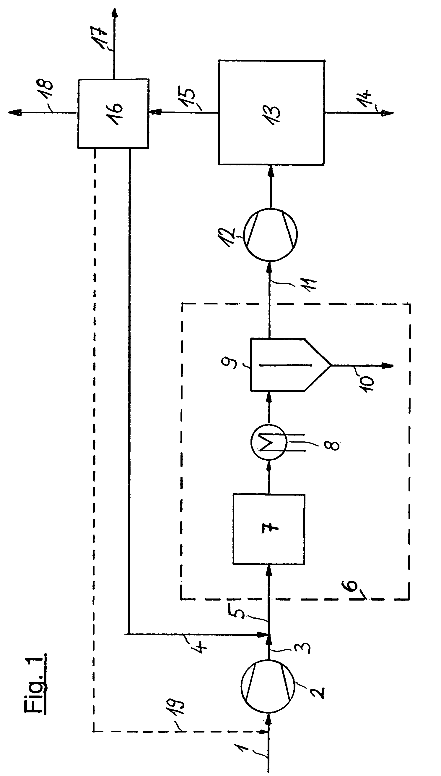
[0034]FIG. 2 illustrates a possibility of integrating, upon the secondary compression in unit 12, residual synthesis gas
stream 11 into secondary synthesis system 13 (shown as broken line), preferably when building a new plant. In this case, the synthesis gas leaving secondary compression unit 12 is fed to the loop at a point downstream of ammonia separation unit 24, but upstream of ammonia reactor 22, as a rule directly upstream of recycle compression unit 21. But it is also possible, as distinct from the way shown in FIG. 2, to arrange synthesis gas
feed point 20 downstream of recycle compression unit 21. The pressure losses caused by the individual process steps within the loop system are compensated by recycle compression unit 21, downstream of which are located ammonia reactor 22, usually consisting of several sections with intermediate cooling, cooling and condensation section 23 for the ammonia produced and ammonia separation unit 24, in which
liquid ammonia 14 is obtained. Purge gas withdrawal point 25 is arranged in the section with the highest concentration of inert ingredients at low temperature, which facilitates the subsequent separation of the residual ammonia in
recovery unit 16 (see FIG. 1). Residual recycle gas 26 is fed to synthesis gas
feed point 20 which completes the loop.
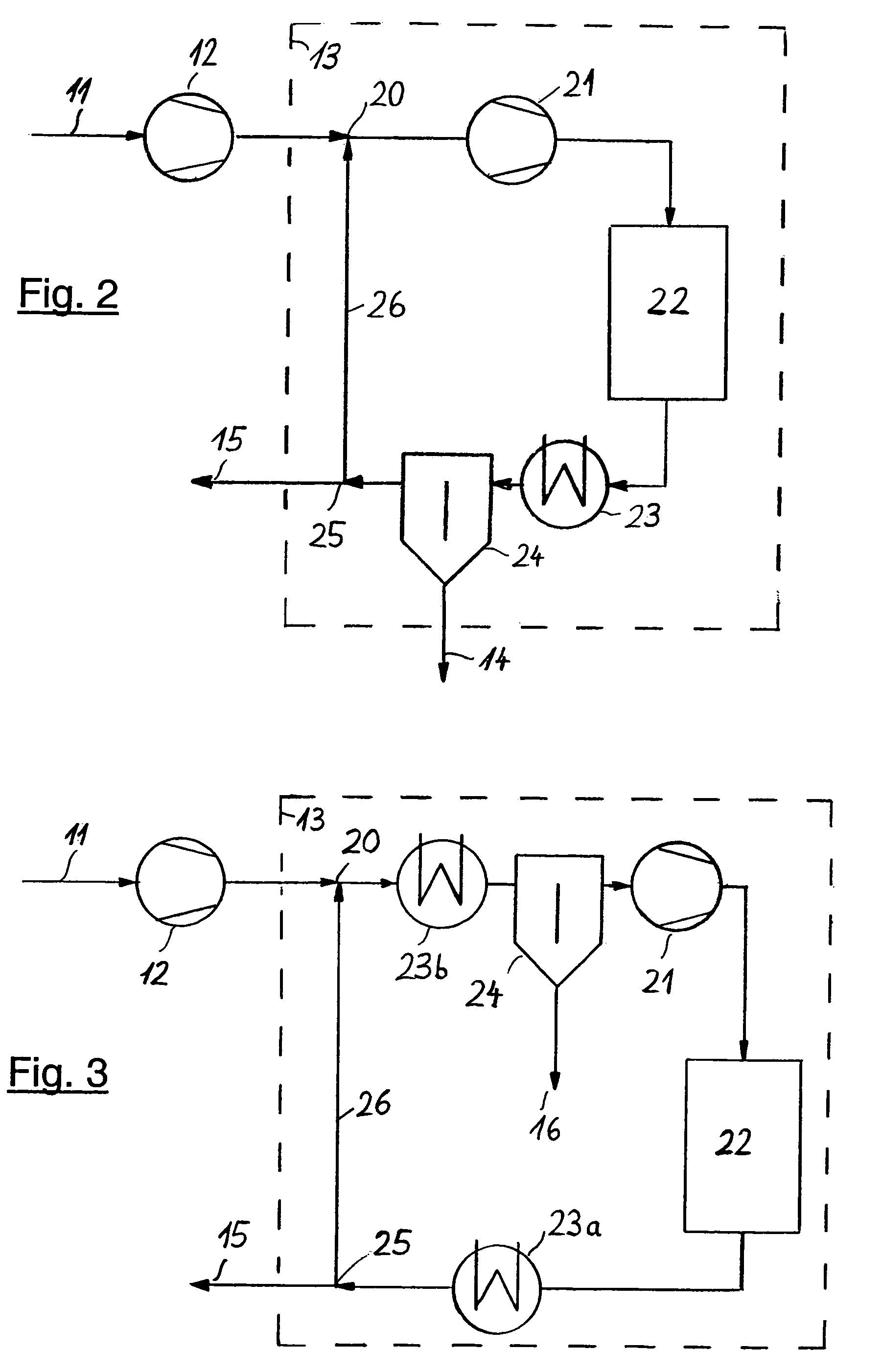
[0035]FIG. 3 illustrates a further possibility of integrating, upon the secondary compression in unit 12, residual synthesis gas stream 11 into secondary synthesis system 13 (shown as broken line), both for a new plant concept as well as for an existing plant operated at
high pressure. Here, the synthesis gas re-compressed in unit 12 is fed to a point located between the high-pressure
reaction system and the product separation. In existing plants, synthesis gas
feed point 20 is usually located in or downstream of cooling and condensation section 23a or 23b, but upstream of ammonia separation unit 24. The pressure losses caused by the individual process steps within the loop system are compensated in downstream recycle compression unit 21. Downstream of said unit 21 there is ammonia reactor 22 which usually consists of several sections with intermediate cooling. Purge gas withdrawal point 25 is also located in the section with the highest concentration of inert ingredients. Residual recycle gas 26 is fed to synthesis gas feed point 20 which completes the loop.

