Single-photon-emission apparatus

Inactive Publication Date: 2006-08-08
MITSUBISHI ELECTRIC CORP
View PDF14 Cites 16 Cited by
  • Summary
  • Abstract
  • Description
  • Claims
  • Application Information

AI Technical Summary

Benefits of technology

[0008]The present invention has been made to solve these problems, and it is an object of the present invention to generate only one photon in one pulse.

Problems solved by technology

However, if the same information is loaded on two or more photons, the unauthorized listener may utilize a part of these photons and the presence of the unauthorized listener may not be able to be detected.
First of all, the conventional method has a drawback in that if two photon pairs exist within the response time of the detector, two signal photons are emitted by a gate operation and two photons exist in a pulse.
In the conventional method, it was unable to control the timing of photon generation within the pulse.
When the detector for detecting the arrival of the photon generates a so-called “dark count pulse,” that is, when the detector outputs pulses due to noises, etc. even when it does not detect the photon, it outputs non-existent light pulse in which no emission photon exists and provided poor efficiency.

Method used


Image

  • Single-photon-emission apparatus
  • Single-photon-emission apparatus
  • Single-photon-emission apparatus

Examples


embodiment 1

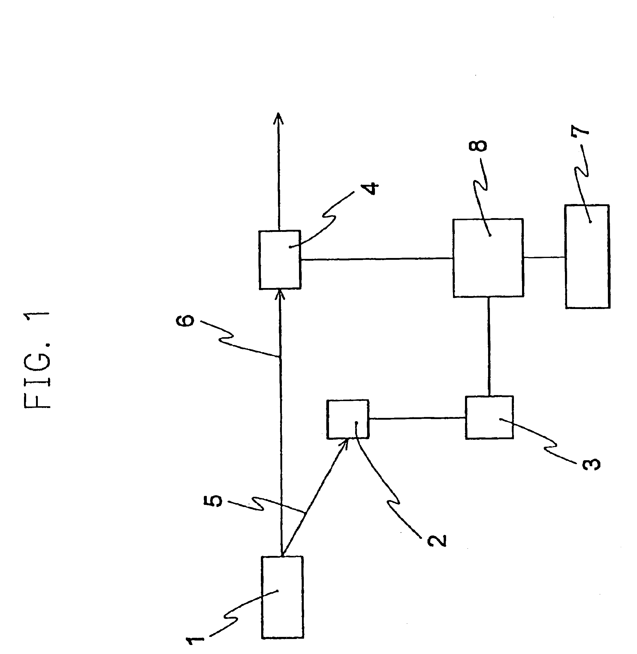
[0037]FIG. 1 is a general arrangement drawing of one embodiment of the invention. In FIG. 1, numeral 1 denotes a photon pair source that generates a photon pair that correlate with the generation time, numeral 2 denotes a photon detector for detecting the idler photon 5, numeral 3 denotes a differential circuit for differentiating the signal pulse generated from the photon detector, numeral 8 a gate device controller section for controlling the gate device 4 in response to the signal from the differentiation circuit 3 and the control clock from the clock generator 7.

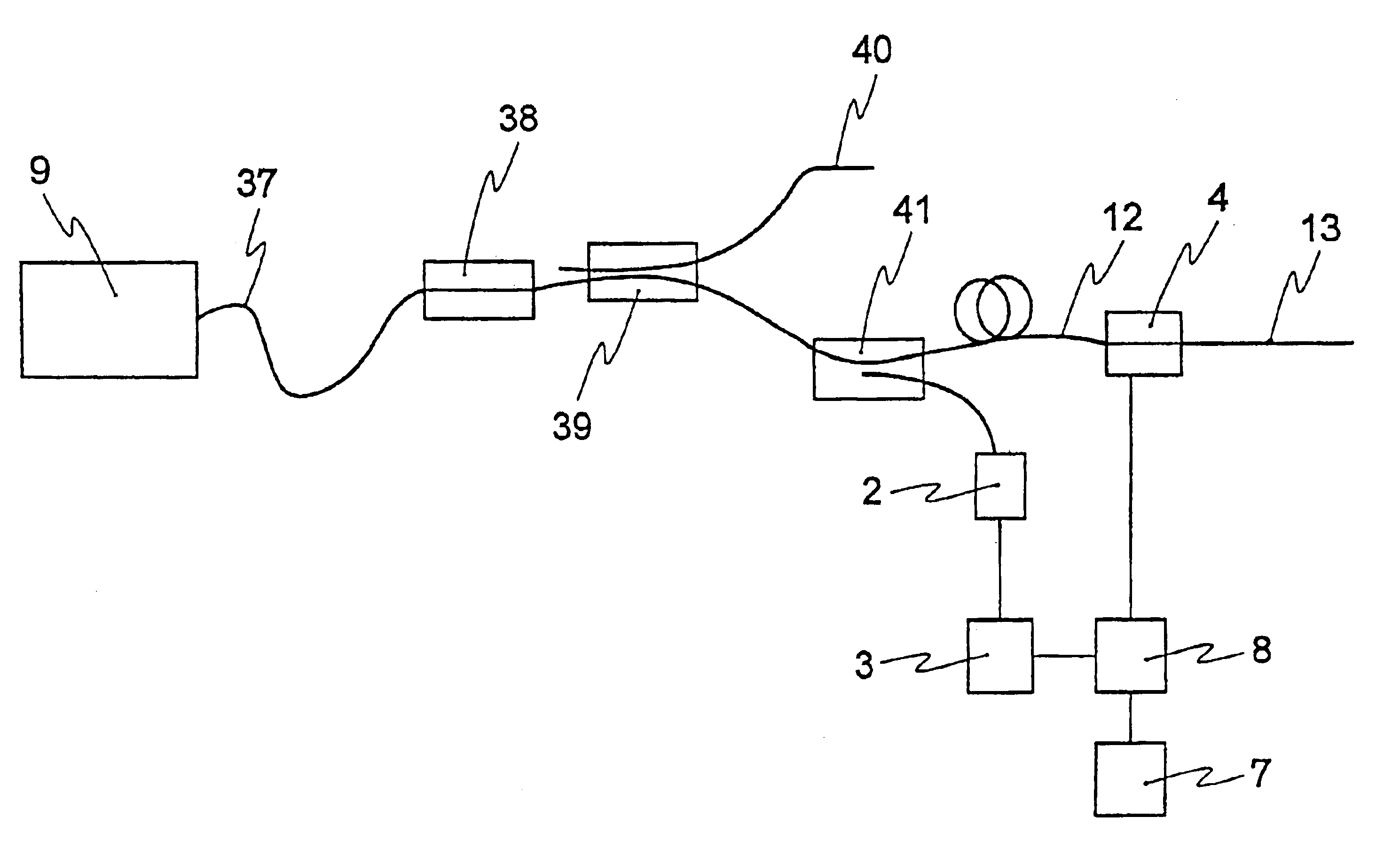
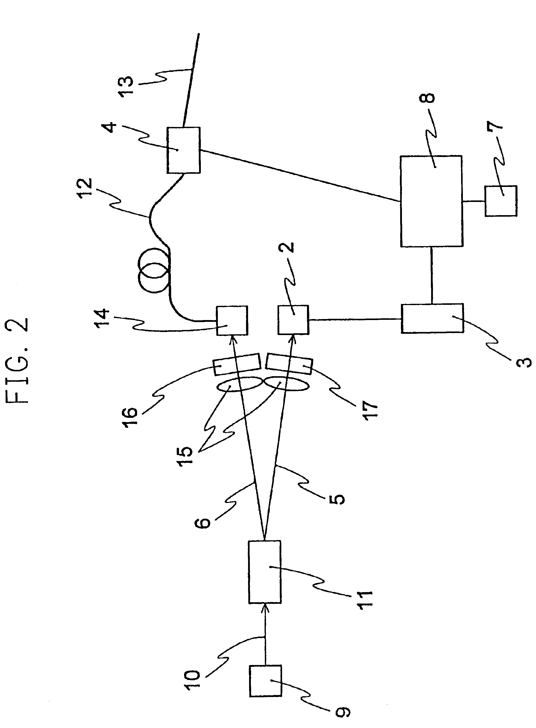
[0038]FIG. 2 shows a detailed configuration of the present embodiment. In this embodiment, an optical pulse that contains only single photon is efficiently generated at a specific timing in the clock.

(Description on Photon Pair Generator)

[0039]In FIG. 2, numeral 9 is a light source of pumping light 10 for pumping the nonlinear optical medium 11. In the nonlinear optical medium 9, the idler photon 5 and the signal photon ...

embodiment 2

[0055]In Embodiment 1, APD of active quenching control was used as a detector 2, but it is also possible to apply voltage for a predetermined time in place of constantly applying voltage exceeding the breakdown voltage to APD. Referring now to FIG. 5, the control condition of such case is described. In FIG. 5, numeral 31 is a graph showing changes of voltage applied to APD with time, numeral 32 a graph showing the signal pulse from APD, and numeral 33 a graph showing differentiation signals outputted from the differentiation circuit 3.

[0056]In Embodiment 1, as described in the section about the active quenching, when the voltage higher than the breakdown voltage is applied to APD, APD has the infinite multiplication to incidence of one photon, and the output of APD enters the saturated breakdown state. In the present embodiment, the voltage applied to APD is controlled in conformity with the clock 18.

[0057]For the period from clock rise-up to about time τ as seen in Numeral 18, the ...

embodiment 3

[0059]In Embodiment 1, the wavelength of signal light generated was 702.2 nm, but needless to say, this wavelength is able to optionally changed by selecting a suitable pumping light source laser and nonlinear optical medium. For example, it is naturally possible to generate wavelengths in the vicinity of 1550 nm, 1310 nm and 800 nm, which are generally adopted to communication using optical fiber.

[0060]The method for generating a photon pair shown in Embodiment 1 (FIG. 3) is a method suited to obtain a photon pair beam with equal wavelengths and small angular dispersion, but it is possible to obtain a photon pair with different wavelengths by changing the optical axis direction of the BBO crystal for other object of use. In such event, the two tuning curves as shown in FIG. 3 come in contact with straight lines that correspond to different wavelengths, respectively. In such event as well, the photons are taken out at an angle, in which the tuning curves as shown in FIG. 3 come in c...


PUM


Abstract

The apparatus includes a photon pair source for generating a photon pair that contains a signal photon and an idler photon and correlates with the generating time, photon detectors for detecting a incidence of idler photons, a clock generator, a gate device controller for generating signals for opening or closing a gate device in a frequency lowering a specific number of times within a specified time defined by the clock, and a gate device for opening or closing the gate in response to the signals from the gate device controller.

Description

TECHNICAL FIELD[0001]The present invention relates to a photon source used for as an example, quantum cryptographic communication system, a transmission system that enables the detection of an unauthorized listener by loading each photon with information.BACKGROUND ART[0002]In the quantum cryptographic communication system, loading each photon with information enables the detection of an unauthorized listener by the quantum mechanical principle. However, if the same information is loaded on two or more photons, the unauthorized listener may utilize a part of these photons and the presence of the unauthorized listener may not be able to be detected. In this way, ideally, a pulse that contains only one photon at maximum must be used. For this kind of pulse, it is popularly practiced to attenuate the light beam from the laser beam source by an attenuator in such a manner that the mean number μof photons per pulse becomes about 0.1. By doing this, the probability to contain two or more ...

Claims


Application Information

Patent Timeline
IPC IPC(8): H04K1/00G02F1/39H04B10/30H04L9/08
CPCG02F1/39H04L9/0852H04B10/00
Inventor TAKEUCHI, SHIGEKI
Owner MITSUBISHI ELECTRIC CORP
Why Eureka
Try Eureka