Surface-coated cutting tool member having hard coating layer exhibiting superior wear resistance during high speed cutting operation and method for forming hard coating layer on surface of cutting tool

a cutting tool and surface coating technology, applied in the field of surface coating cutting tool parts, can solve the problems of significant progress in the wear resistance of the hard coating layer of the tool, and relatively short operation li

Inactive Publication Date: 2006-08-22
MITSUBISHI MATERIALS CORP
View PDF13 Cites 36 Cited by
  • Summary
  • Abstract
  • Description
  • Claims
  • Application Information

AI Technical Summary

Benefits of technology

[0020]The average thickness was set from 1 to 15 μm because when the thickness of the layer is less than 1 μm, a desired wear resistance cannot be ensured, and in contrast, when the average thickness is greater than 15 μm, the cutting edge tends to be chipped.

Problems solved by technology

With regard to the above-mentioned conventional cutting tool, no significant problem is encountered when such a tool is used under normal cutting conditions; however, when such a tool is used under high speed cutting conditions in which a significant amount of heat is generated, wear of the hard coating layer of the tool is significantly progressed, which leads to a relatively short operation life.

Method used


Image

  • Surface-coated cutting tool member having hard coating layer exhibiting superior wear resistance during high speed cutting operation and method for forming hard coating layer on surface of cutting tool
  • Surface-coated cutting tool member having hard coating layer exhibiting superior wear resistance during high speed cutting operation and method for forming hard coating layer on surface of cutting tool
  • Surface-coated cutting tool member having hard coating layer exhibiting superior wear resistance during high speed cutting operation and method for forming hard coating layer on surface of cutting tool

Examples


embodiment 1

[0027]First, ingredient powders, i.e., powders of WC, TiC, ZrC, VC, TaC, NbC, Cr3C2, TiN, TaN, and Co, all of which have an average grain size in a range from 1 to 3 μm, were prepared and mixed in accordance with blending ratios shown in TABLE 1. The ingredient powders were mixed under wet conditions using a ball mill for 72 hours, were dried, and were compacted under pressure of 100 MPa so as to form green compacts. The green compacts were held in a vacuum of 6 Pa at a temperature of 1400° C. for 1 hour so as to be sintered. After sintering, a honing process, in which a radius is set to be 0.03, is applied to cutting edge portions of each of the sintered compacts so as to obtain hard metal substrates A-1 to A-10 of WC based hard metal, each of which had an insert shape defined as CNMG120408 in the ISO standard.

[0028]Furthermore, ingredient powders, i.e., powders of TiCN (TiC / TiN=50 / 50 when expressed by weight ratio), Mo2C, ZrC, NbC, TaC, WC, Co, and Ni, all of which had an average ...

embodiment 2

[0053]Ingredient powders, i.e., medium coarse powder of WC having an average grain size of 5.5 μm, fine powder of WC having an average grain size of 0.8 μm, powder of TaC having an average grain size of 1.3 μm, powder of NbC having an average grain size of 1.2 μm, powder of ZrC having an average grain size of 1.2 μm, powder of Cr3C2 having an average grain size of 2.3 μm, powder of VC having an average grain size of 1.5 μm, powder of (Ti, W)C having an average grain size of 1.0 μm, and powder of Co having an average grain size of 1.8 μm, were prepared. The ingredient powders were blended according to the blending ratios shown in TABLE 7, were mixed in acetone after adding wax for 24 hours using a ball mill, were subjected to depressurized drying, and were compacted under a pressure of 100 MPa so as to obtain various green compacts having predetermined shapes. The green compacts were held in a vacuum of 6 Pa while increasing temperature from 1370° C. to 1470° C. at a temperature incr...

embodiment 3

[0077]The three types of sintered bars, i.e., the bars having a diameter of 8 mm (hard metal substrates C-1 to C-3), the bars having a diameter of 13 mm (hard metal substrates C-4 to C-6), and the bars having a diameter of 26 mm (hard metal substrates C-7 and C-8), fabricated in Embodiment 2 were subjected to grinding so as to obtain hard metal substrates (drills) D-1 to D-8, and more specifically, to obtain hard metal substrates D-1 to D-3 having a fluted portion size of 4 mm×13 mm (diameter×length), hard metal substrates D-4 to D-6 having a fluted portion size of 8 mm×22 mm, and hard metal substrates D-7 and D-8 having a fluted portion size of 16 mm×45 mm.

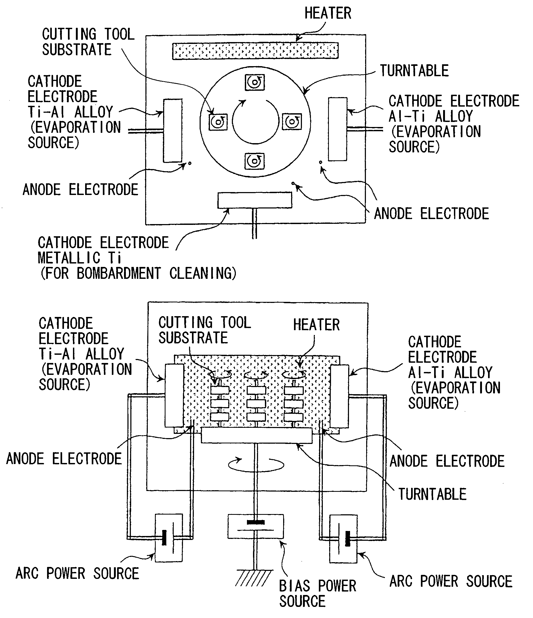
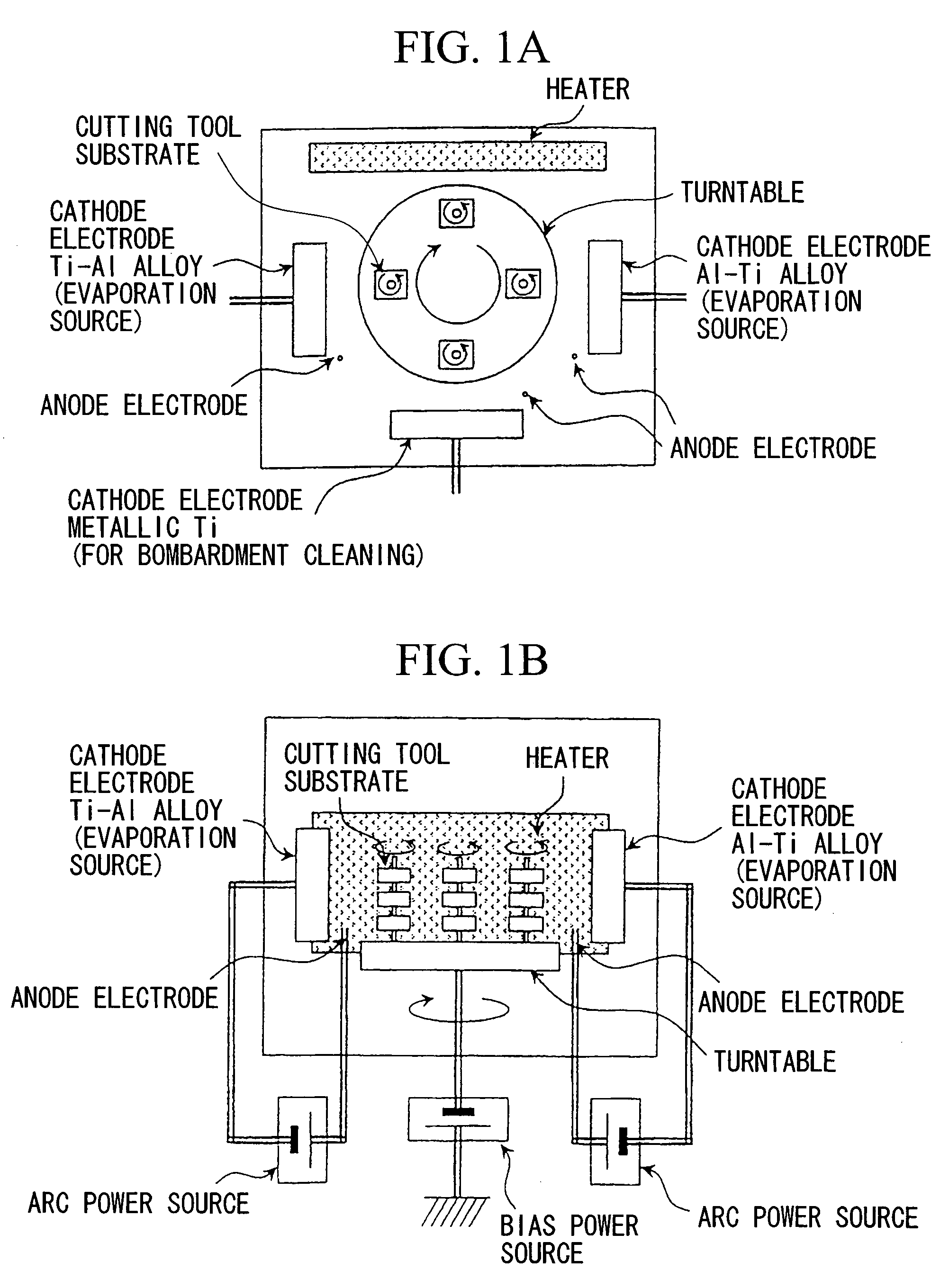
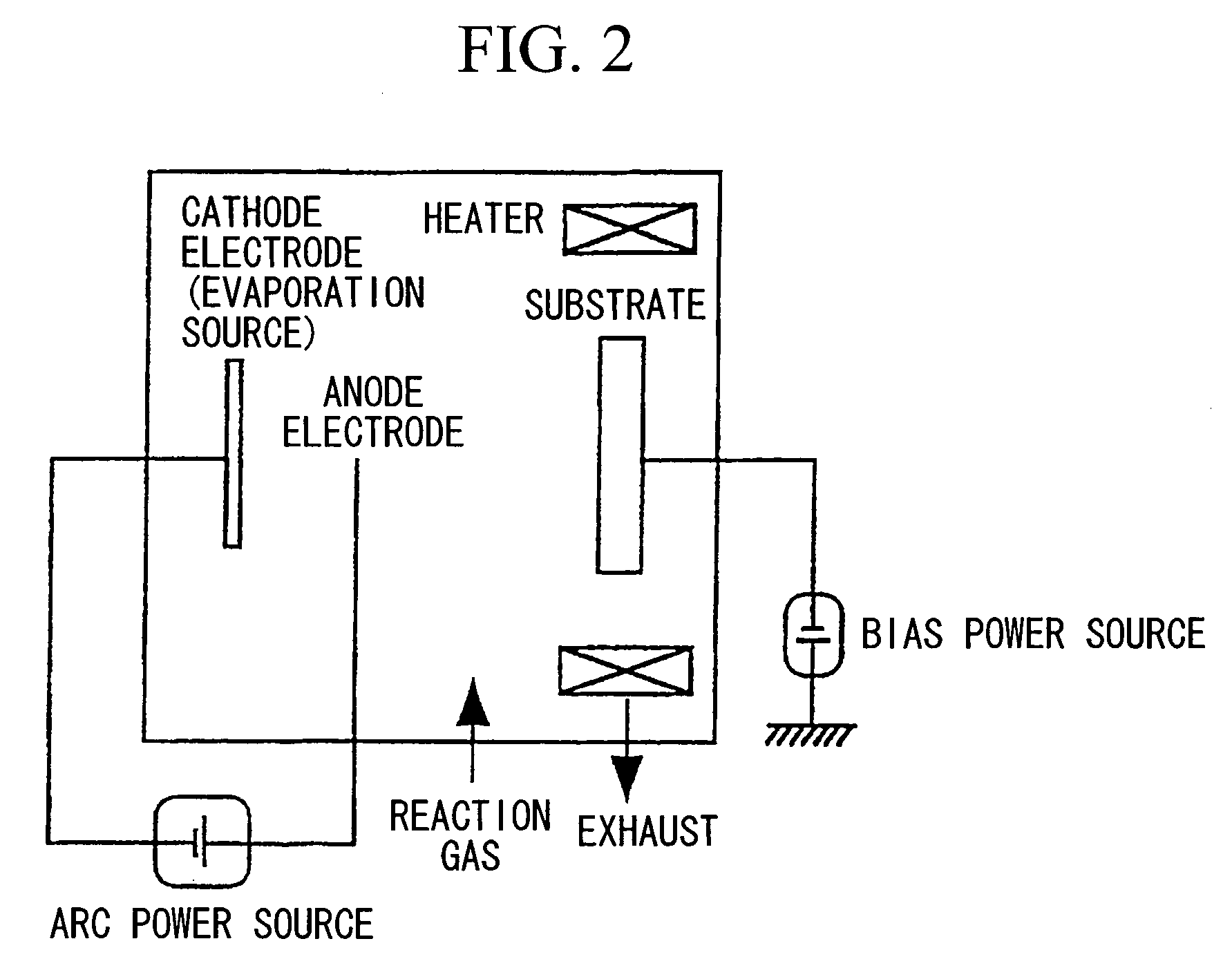
[0078]Next, honing processes were applied to the cutting edges of the hard metal substrates (drills) D-1 to D-8, the hard metal substrates D-1 to D-8 were subjected to ultrasonic cleaning in acetone, were dried, and were accommodated in the arc ion plating apparatus shown in FIGS. 1A and 1B, and then the method of the present inv...


PUM

PropertyMeasurementUnit
thicknessaaaaaaaaaa
distanceaaaaaaaaaa
temperatureaaaaaaaaaa

Abstract

A surface-coated cutting tool member includes a tungsten carbide based cemented carbide substrate, a titanium carbonitride based cermet substrate, or a cubic boron nitride based sintered substrate; and a hard coating layer of a nitride compound containing aluminum and titanium, formed on a surface of the substrate using a physical vapor deposition method in an overall average thickness of 1 to 15 μm. The hard coating layer has a component concentration profile in which maximum aluminum containing points and minimum aluminum containing points appear alternatingly and repeatedly at a distance from 0.01 to 0.1 μm in a direction of thickness of the hard coating layer. The amount of contained aluminum (or titanium) is changed from the maximum aluminum containing points to the minimum aluminum containing points. The maximum aluminum containing points satisfy a formula: (AlXTi1−X)N, wherein X is between 0.70 to 0.95. The minimum aluminum containing points satisfy a formula: (AlYTi1−Y)N, wherein Y is between 0.40 to 0.65.

Description

CROSS-REFERENCE TO PRIOR APPLICATION[0001]This is a U.S. national phase application under 35 U.S.C. §371 of International Patent Application No. PCT / JP03 / 00220 filed Jan. 14, 2003, and claims the benefit of Japanese Patent Application Nos. 2002-11478 filed Jan. 21, 2002; 2002-49893 filed Feb. 26, 2002 and 2002-60208 filed Mar. 6, 2002 which are incorporated by reference herein. The International Application was published in Japanese on Jul. 31, 2003 as WO 03 / 061884 A1 under PCT Article 21(2).TECHNICAL FIELD[0002]The present invention relates to a surface-coated cutting tool member (hereinafter referred to as a coated cutting tool) having a hard coating layer exhibiting superior high temperature properties, and thereby exhibiting a superior wear resistance during a high speed cutting operation for various kinds of steels and cast irons in which a significant amount of heat is generated.[0003]Moreover, the present invention relates to a method for forming the above-mentioned hard coat...

Claims


Application Information

Patent Timeline
Patent Type & Authority Patents(United States)
IPC IPC(8): B23B27/14C23C14/06C23C30/00
CPCC23C14/0641C23C30/005Y10T428/24942Y10T428/24975Y10T428/265B23B27/14C23C14/06
Inventor SATO, KAZUNORIKONDO, AKIHIROTANAKA, YUSUKE
Owner MITSUBISHI MATERIALS CORP
Why Eureka
Try Eureka