Stability of ion beam generated alignment layers by surface modification

Inactive Publication Date: 2006-08-29
IBM CORP
View PDF21 Cites 5 Cited by
  • Summary
  • Abstract
  • Description
  • Claims
  • Application Information

AI Technical Summary

Benefits of technology

[0010]Methods for inducing chemical changes to an alignment layer surface are described herein. Surface modification to an alignment layer surface, such as for example, a diamond like carbon (DLC) surface is carried out to enhance time stability of liquid crystal pretilt angle and further to fine-tune the pretilt angle and other properties related to the alignment of liquid crystal (LC) through interaction of the liquid crystal with the alignment layer surface.

Problems solved by technology

In addition, the pretilt angle is not stable under ultra-violet (UV) or violet irradiation.
As a result, the pretilt angle will degrade.

Method used


Image

  • Stability of ion beam generated alignment layers by surface modification
  • Stability of ion beam generated alignment layers by surface modification
  • Stability of ion beam generated alignment layers by surface modification

Examples


Embodiment Construction

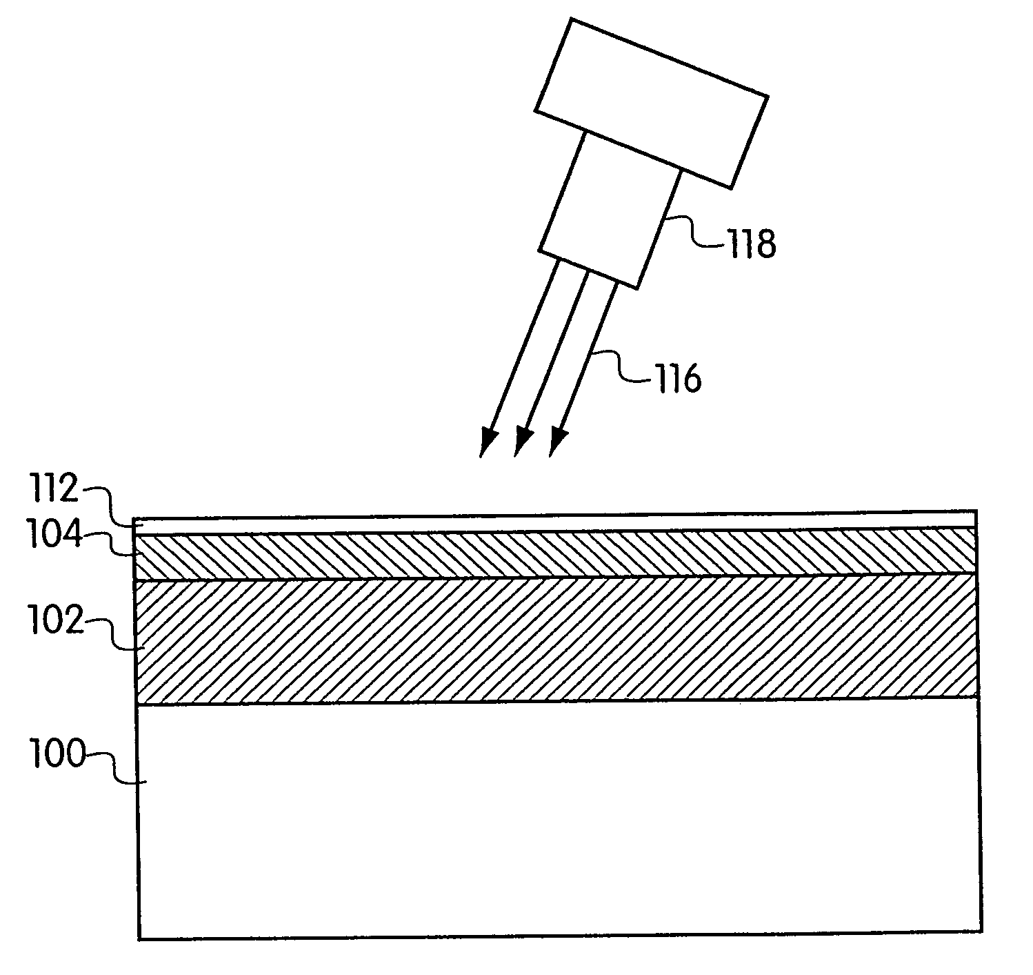
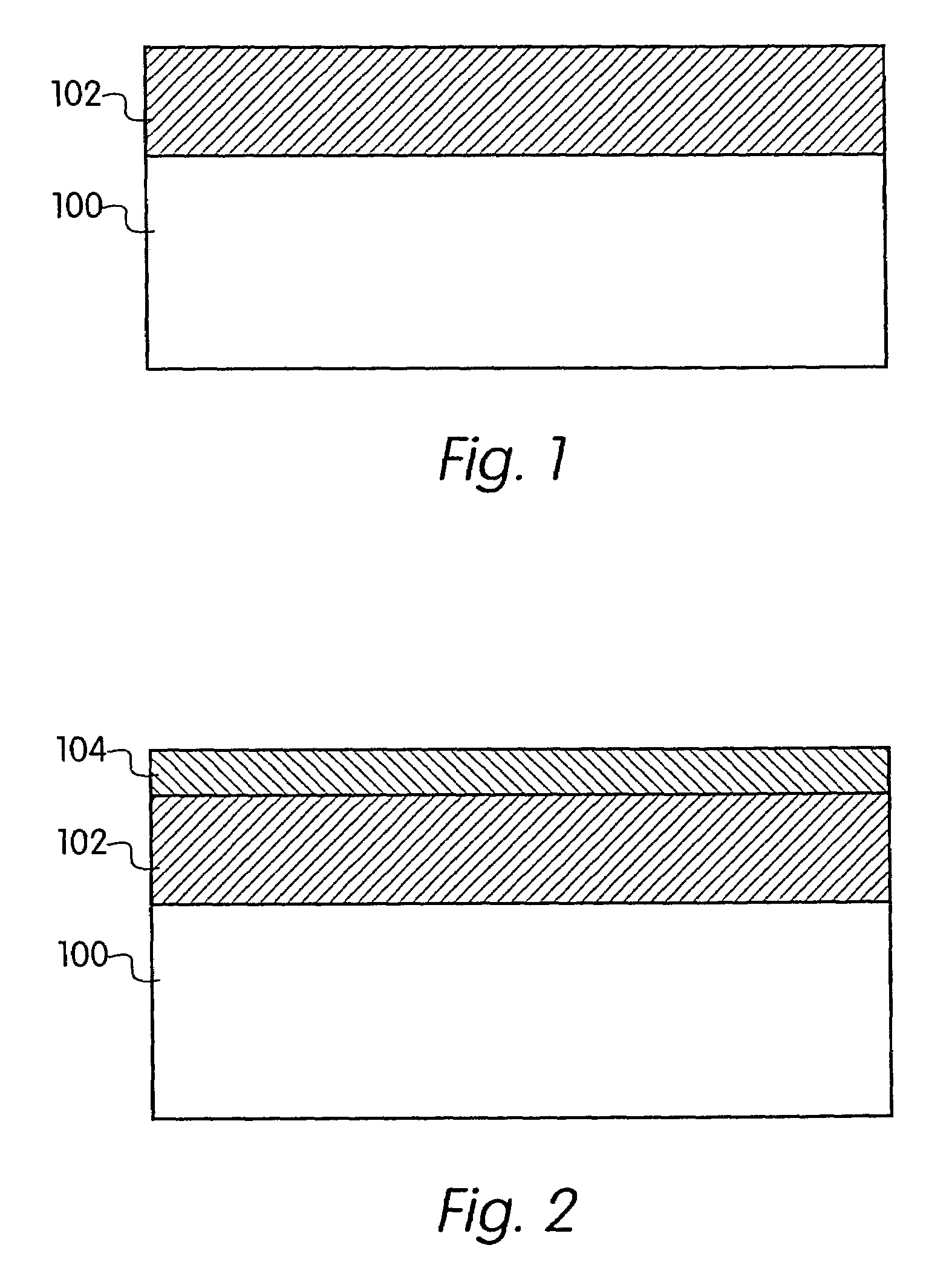
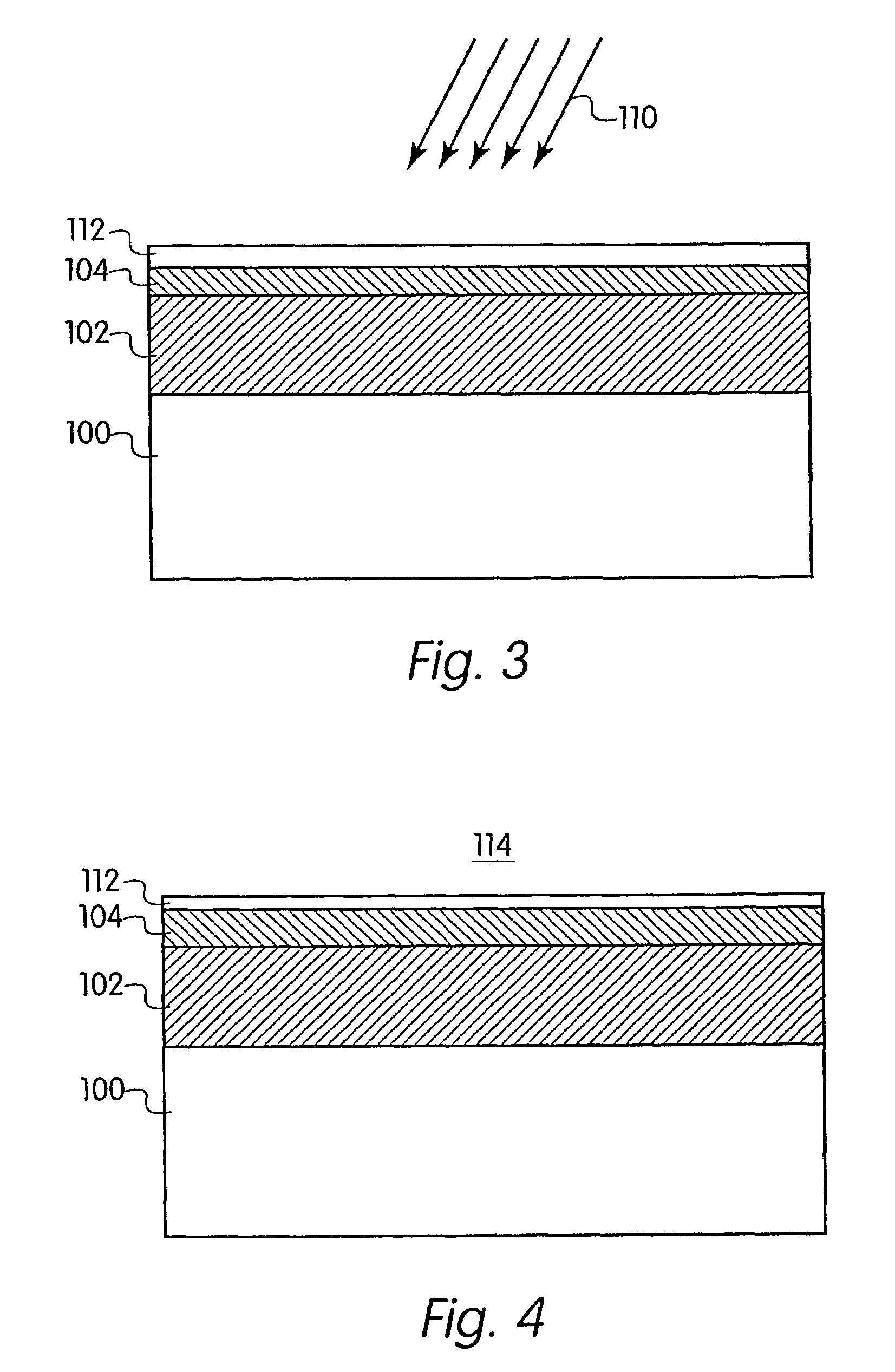
[0031]The present invention includes methods of surface modification to stabilize and otherwise fine tune ion beam treated surfaces. Surface treated in accordance with the invention may include, for example, diamond like carbon (DLC), amorphous hydrogenated silicon, SiC, SiO2, glass, Si3N4, Al203, CeO2, SnO2, indium tin oxide (ITO) and ZnTiO2 films or other materials employed in the ion beam treated alignment layers. Surface modification is achieved by saturating dangling bonds on the surface of the ion beam (IB) film. The IB film may be modified in a plurality of ways in accordance with the present invention. In preferred embodiments, surface modification and / or dangling bond saturation may be performed during IB treatment by introducing other reactive species originating from, for example, nitrogen (N2), fluorine (F2), tetrafluoromethane (CF4), hydrogen (H2), silicon (e.g., from silane), carbon (C), Oxygen (O2). These species may be mixed with or replace Ar in an ion beam. In anot...


PUM


Abstract

A method for preparing an alignment layer surface provides a surface on the alignment layer. The surface is bombarded with ions, and reactive gas is introduced to the ion beam to saturate dangling bonds on the surface. Another method for preparing an alignment layer surface provides a surface on the alignment layer. The surface is bombarded with ions and quenched with a reactive component to saturate dangling bonds on the surface.

Description

CROSS-REFERENCE TO RELATED APPLICATION[0001]This application is a divisional of U.S. patent application Ser. No. 09 / 726,951, now U.S. Pat. No. 6,665,033 filed on Nov. 30, 2000, the disclosure of which is herein incorporated by reference in its entirety.BACKGROUND OF THE INVENTION[0002]1. Field of the Invention[0003]The present invention relates to liquid crystal displays, and more particularly to methods for forming a stable alignment layer created by ion beam irradiation of a carbon film.[0004]2. Description of the Related Art[0005]Liquid crystal (LC) material employed in liquid crystal displays typically rely on alignment layers to establish a stable pretilt angle and other parameters such as anchoring energy for the liquid crystal material. Typically, the alignment of the liquid crystals for flat panel liquid crystal displays (LCD) is accomplished by placing a thin film of LC material on a mechanically rubbed polyimide film coated on a suitable substrate. Limitations imposed by t...

Claims


Application Information

Patent Timeline
IPC IPC(8): C23C14/02C23C14/14C23C14/48C23C14/58G02F1/1337B01J19/12C01B31/02
CPCG02F1/13378G02F1/1337
Inventor CALLEGARI, ALESSANDRO C.CHAUDHARI, PRAVEENDOANY, FUAD E.DOYLE, JAMES P.GALLIGAN, EILEEN A.GLOWNIA, JAMES H.HOUGHAM, GARETH G.LACEY, JAMES A.LIEN, SHUI-CHIHLU, MINHUAROSENBLUTH, ALAN E.YANG, KEI-HSIUNG
Owner IBM CORP
Why Eureka
Try Eureka