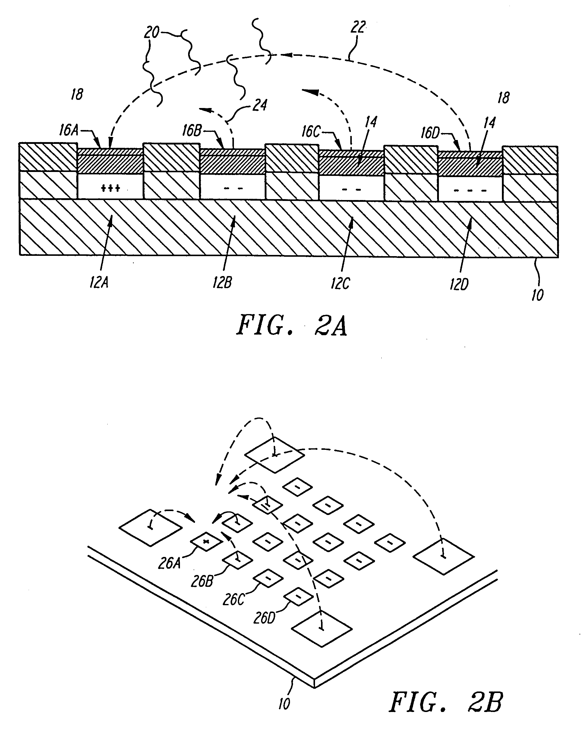
[0021]The device is able to control and actively carry out a variety of assays and reactions. Analytes or reactants can be transported by
free field electrophoresis to any specific micro-location where the analytes or reactants are effectively concentrated and reacted with the specific binding entity at the micro-location. In the case of hybridization analysis, the sensitivity for detecting a specific
analyte or reactant is improved because hybridization reactants are concentrated at a specific microscopic location. Any un-bound analytes or reactants can be removed by reversing the polarity of a micro-location. Thus, the device also improves the specificity of the reactions. Basic devices for nucleic acid hybridization and other analyses are alternatively referred to as APEX devices, which stands for addressable programmable electronic matrix.
[0022]In one aspect of this invention, the APEX device is utilized with a fluidic system in which a sample is flowed over the APEX device during operation in the preferred embodiment, the fluidic system includes a
flow cell and a
liquid waste containment vessel. The sample is provided to the input to the
flow cell and directed across the active areas of the APEX system. Preferably, a defined volume is provided within the flow
cell, preferably in the range from 5 to 10 microliters. A flowing sample over the
active detection device provides important advantages in the hybridization analysis of dilute, concentrated and / or relatively complex DNA samples. For example, if the total
sample volume is relatively large compared to the same chamber volume, flowing of the sample provides more complete analysis of the entire sample. Alternatively, where the
sample volume is relatively small, and / or the DNA is relatively concentrated,
dilution is indicated in order to reduce the
viscosity of the sample.
[0026]A controller for the device (or system) provides for individual control of various aspects of the device. When an APEX device or
chip containing addressable microscopic locations is utilized, the controller permits individual microlocations to be controlled electronically so as to direct the transport and attachment of specific binding entities to that location. The device may carry out multi-step and multiplex reactions with complete and precise electronic control, preferably under control of a
microprocessor based component. The rate, specificity, and sensitivity of multi-step and multiplex reactions are greatly improved at the specific microlocations on the device. The controller interfaces with a user via input / output devices, such as a display and keyboard input. Preferably, a
graphical user interface is adapted for ease of use. The input / output devices are connected to a controller, which in turn controls the electrical status of the addressable electronic locations on the system. Specifically, the controller directs a power supply / waveform generator to generate the electronic status of the various microlocations. Optionally, an interface is used between the power supply / waveform generator and the APEX device or system. The interface preferably comprises a
bank of relays subject to the controller via a multifunction input / output connection. The relays preferably serve to connect the power supply / waveform generator to the APEX device by controlling the connection as to its polarity, the presence or absence of a connection and the amount of potential or current supply to the individual location. The controller preferably controls the illumination source directed at the hybridization system. A
detector,
image processing and
data analysis system are optically coupled to the APEX device. In the preferred embodiment, a fluorescent
microscope receives and magnifies the image from the hybridization events occurring on the various micro-locations of the device. The emissions are optically filtered and detected by a
charge coupled device (CCD) array or
microchannel plate detector. The image is then stored and analyzed. Preferably, the results are displayed to the user on the monitor.
[0030]Electronic control of the individual microlocations may be done so as to control the
voltage or the current. When one aspect is set, the other may be monitored. For example, when
voltage is set, the current may be monitored. The
voltage and / or current may be applied in a
direct current mode, or may vary with time. For example, pulsed currents or DC biases may be advantageously utilized. The pulsed system may be advantageously utilized with the fluidic system, especially the flow
cell design. By coordinating the
pulse sequence and flow rate, the sample can be more effectively interrogated throughout the
sample volume. Additionally, even for non-flow situations, such as where there are relatively high amounts of non-target material, e.g., DNA, which without pulsing might overwhelm the activated test sites. Pulse techniques generally result in higher target mobility rates at higher
ionic strength, reduced probe burn-out effects, improved hybridization efficiencies, improved discrimination of point mutations and enhanced DNA fingerprinting.
[0031]In yet another aspect of this invention, it has been surprisingly discovered that the
fluorescence signal obtained during the electronic denaturation of DNA hybrids is perturbed at or around electronic and power levels which are associated with dehybridization. Specifically, the
fluorescence signal perturbation results in a rise or spike in
fluorescence intensity prior to dehybridization of fluorescently labelled probes from a capture sequence attached to an APEX pad. The
power level, amplitude and slope of this fluorescence spike provide analytical tools for diagnosis. The combination of the fluorescence perturbation with other measurements also indicative of the hybridization match / mismatch state, such as consideration of the electronic melting (50% fluorescence decrease during electronic stringency control) can in combination provide a more efficient and reliable hybridization match / mismatch analysis.
[0038]It is yet another object of this invention to provide a system which is capable of manufacture using conventional techniques, with high efficiencies and low cost.

