Fuel cell power generation equipment and a device using the same

a technology of power generation equipment and fuel cell, which is applied in the direction of secondary cell servicing/maintenance, cell components, cell component details, etc., can solve the problems of system insufficient to achieve miniaturization, long charge time, and many problems of secondary batteries for a long continuous drive. , to achieve the effect of prolonging the service time of these electronics devices

Inactive Publication Date: 2006-09-12
HITACHI LTD
View PDF24 Cites 29 Cited by
  • Summary
  • Abstract
  • Description
  • Claims
  • Application Information

AI Technical Summary

Benefits of technology

[0021]On the other hand, an oxidizing agent is fed by a diffusion of oxygen in air to each unit cell having a power generation part at outer wall surface of the liquid fuel container. A longer power generation can be continued by using a liquid fuel having a high volume energy density such as aqueous methanol solution as a fuel in comparison with the case when hydrogen gas is used as a fuel in the same volume of container.
[0022]By using a power source comprising a fuel cell in

Problems solved by technology

However, secondary batteries still have many problems for a long continuous drive of portable electronics devices because charging is indispensable after consuming a certain amount of power, and a charging equipment and a relatively longer charge time are required.
However, in the application to a power source for portable electronics devices, a large volume of fuel tank should be provided due to a lower volume energy density of a fuel because the fuel used is hydrogen gas.
This system also requires auxiliary equipment such as an equipment to feed a fuel gas or an oxidizing gent gas (such as air) to a power generation equipment or to humidify electrolyte membr

Method used


Image

  • Fuel cell power generation equipment and a device using the same
  • Fuel cell power generation equipment and a device using the same
  • Fuel cell power generation equipment and a device using the same

Examples


example 1

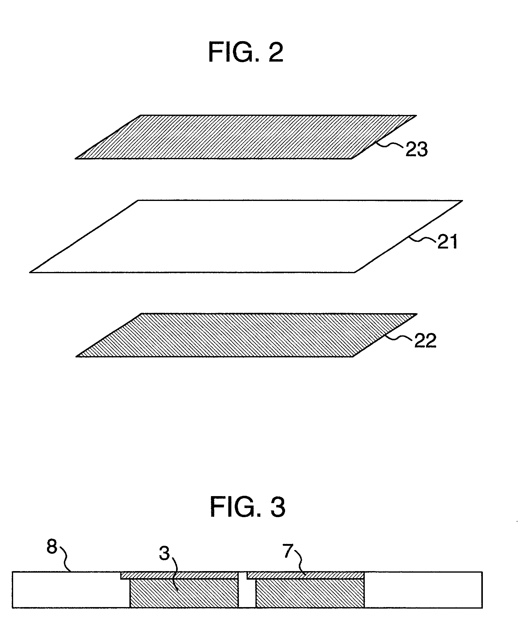
[0105]FIG. 11 shows a structure of MEA in accordance with this Example. MEA is formed by joining an anode layer 22 and a cathode layer 23 using an electrolyte resin as a binder so that they are overlapped with both sides of an electrolyte membrane 21.

[0106]As an anode layer, a porous membrane of about 20 μm thickness was formed by screen printing of a slurry, prepared by 50% by weight of fine powder catalyst of platinum / ruthenium alloy with an atomic ratio of platinum / ruthenium being 1 / 1, dispersed and supported on carbon carrier, and 30% by weight of perfluorocarbone sulfonic acid electrolyte (Nafion 117) in a water / alcohol mixed solvent (water:isopropanol:n-propanol is 20:40:40 ratio by weight) as a binder.

[0107]As a cathode layer, a porous membrane of about 25 μm thickness was formed by screen printing of a slurry, prepared by 30% by weight of fine powder catalyst of platinum supported on carbon carrier and an electrolyte in a water / alcohol mixed solvent as a binder.

[0108]The abo...

example 2

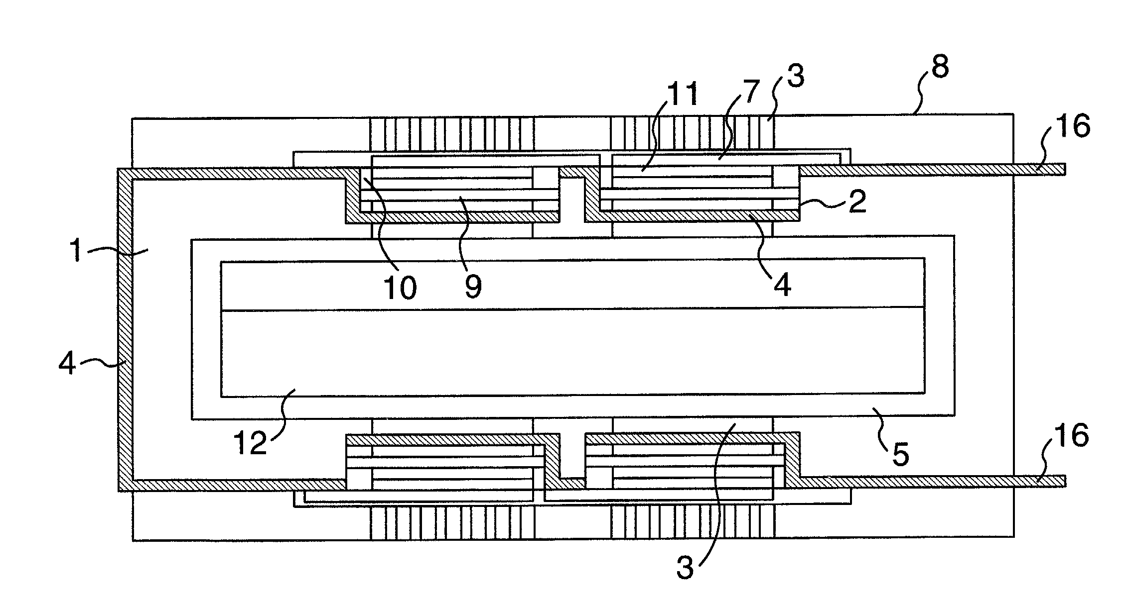
[0129]FIG. 15 shows a cross-sectional structure of a rectangular type and low voltage type of power generation equipment using methanol as a fuel in accordance with this Example, and FIG. 16 shows outline of a mounting method for fuel cells. MEA was prepared by an almost similar method as in Example 1. A porous membrane of about 20 μm thickness was formed on a polyimide film with the dimensions of 30 mm width×50 mm length by screen printing using a slurry, which was prepared by mixing a catalyst powder of 50% by weight of platinum / ruthenium alloy fine particles, an atomic ratio of platinum / ruthenium being 1 / 1, dispersed and supported on carbon carrier, 30% by weight of perfluorocarbon sulfonic acid electrolyte (Nafion 117) as a binder and a water / alcohol mixed solvent (water:isopropanol:n-propanol was 20:40:40, ratio by weight), followed by drying at 90° C. for 3 hours to get an anode porous layer.

[0130]A porous cathode layer of about 25 μm thickness was formed on a polyimide film w...

example 3

[0144]In this Example, a fuel cell with a metal fuel container coated with epoxy resin as a platform will be described.

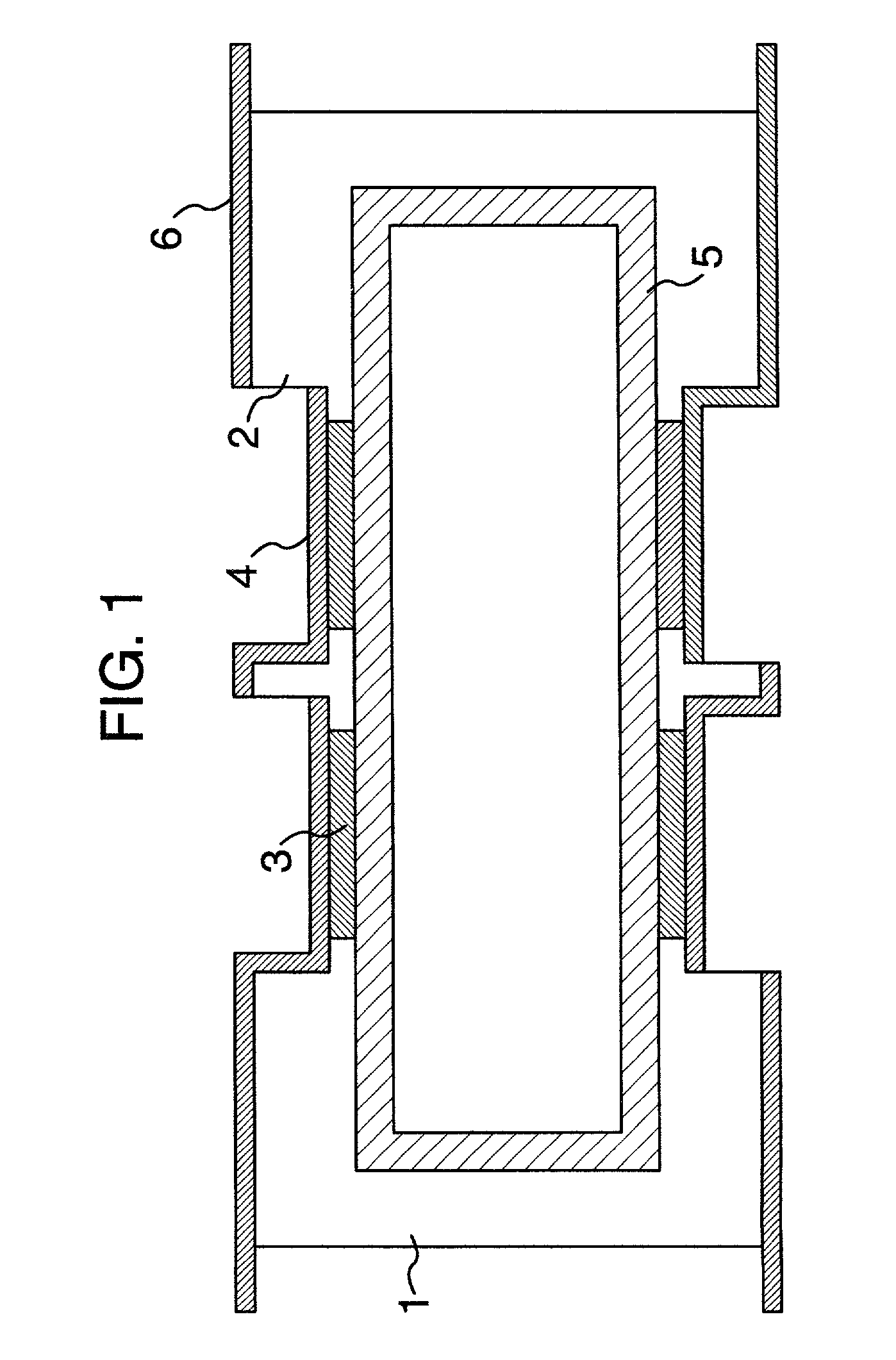
[0145]MEA and a cathode side diffusion layer were prepared in the same way as in Example 2A. A fuel container made of SUS 304 was prepared with the outer dimensions of 22 mm width×79 mm length×23 mm height and the thickness of 0.3 mm, as shown in FIG. 17. The container is composed of a frame and an upper and a bottom lids having 4 faces of press formed fuel cell mounting parts 2 with the dimensions of 16 mm width×16 mm length×0.5 mm depth.

[0146]A slit of 0.5 mm width×10 mm length was provided by punching as a diffusion hole 3 in a part having the size of 10 mm width×10 mm length in the center of a fuel cell mounting part 2. Air vent holes 15 with an inner diameter of 1 mm made of SUS 304 were mounted without using a gas / liquid separation membrane in corner parts of an upper and a bottom lids. Using these parts, a fuel container 1 was prepared by weld-sealing, after ...


PUM


Abstract

An object of the present invention is to obtain a fuel cell power generation equipment most suitable for a portable power source without requiring any auxiliary equipment such as a separator and a fluid feeder. According to the present invention, a fuel cell power generation equipment is provided, in which an anode for oxidizing fuel and a cathode for reducing oxygen are formed with an electrolyte membrane in between and liquid is used as a fuel, wherein one or more air vent holes are provided on a wall surface of a fuel container 1, multiple unit cells having an electrolyte membrane, an anode and a cathode are mounted on a wall surface of said fuel container, and the unit cells are electrically connected each other.

Description

BACKGROUND OF THE INVENTION[0001]The present invention relates to a fuel cell power generation equipment comprising an anode, an electrolyte membrane, a cathode and a diffusion layer, wherein fuel is oxidized at an anode and oxygen is reduced at a cathode, in particular, compact type portable power source using liquid fuel such as methanol as a fuel and mobile electronic devices using this power source.[0002]Recent progress in electronics technology has contributed to miniaturizations of telephone set, notebook type personal computer, audio visual devices or mobile information terminal devices, and their use is increasingly prevailing as portable electronics devices.[0003]Heretofore, these portable electronics devices were driven by a secondary battery, and have been developed through the appearances of new type secondary batteries from sealed lead battery to Ni / Cd, Ni / hydrogen and further Li ion batteries, and modifications to more compact and light weight types and higher energy d...

Claims


Application Information

Patent Timeline
IPC IPC(8): H01M2/00H01M8/00H01M8/10H01M8/02H01M4/86H01M8/04H01M8/24H01M10/46H01M16/00H02J7/00
CPCH01M4/8631H01M8/1009H01M8/2455H01M16/003H01M8/04201H01M8/1011Y02E60/521H01M10/46H01M2300/0082H01M8/1097Y02E60/10Y02E60/50H01M8/02H01M8/24
Inventor KAMO, TOMOICHIOHARA, SHUICHIMORISHIMA, MAKOTO
Owner HITACHI LTD
Why Eureka
Try Eureka