Honeycomb filter and ceramic filter assembly

a technology of ceramic filter and honeycomb, which is applied in the direction of machines/engines, chemical/physical processes, domestic applications, etc., can solve the problems of power loss, affecting the environment, and reducing the number of sperms,

Inactive Publication Date: 2006-09-26
IBIDEN CO LTD
View PDF38 Cites 192 Cited by
  • Summary
  • Abstract
  • Description
  • Claims
  • Application Information

AI Technical Summary

Problems solved by technology

Various substances suspended in the exhaust gas that is emitted, especially from diesel engines, cause pollution and severely affect the environment.
Further, recently reported research results have shown that the fine particles suspended in gas emissions (diesel particulates) may cause allergies or decrease sperm counts.
A main cause of power loss is the resistance the exhaust gas encounters when passing through a filter.
However, the honeycomb filter, which is made of a sintered porous silicon carbide body, is vulnerable to thermal impacts.
Thus, larger filters are liable to crack.
However, in the prior art, there is a shortcoming in that the fine particles trapped in the ceramic filter assembly do not burn completely and some of the fine particles remain unburned.
Accordingly, the efficiency for processing the exhaust gas is low.
Further, the honeycomb filter of the prior art has corners.
Thus, there is a tendency of stress concentrating on the corners of the outer surface and chipping the corners.
Further, the seal layer may crack and break the ceramic filter assembly from the corners thereby damaging the entire ceramic filter assembly.
Even if the assembly does not break, there is a shortcoming in that leakage of the exhaust gas may decrease the processing efficiency.
During usage of the filter assembly, a high temperature difference between the honeycomb filters may cause thermal stress to crack the honeycomb filters and break the entire assembly.
Thus, even if the assembly is accommodated in the casing with the thermal insulative material attached to the peripheral surface of the assembly, gaps are formed in the longitudinal direction of the filters.
Thus, exhaust gas tends to leak through the gaps.
This lowers the processing efficiency of the exhaust gas.
With regard to diesel particulates trapped in the honeycomb filter, it has been confirmed that particulates having a small diameter have a high lung attaching rate and increase the risk to health.
However, when the pore diameter and the porosity of the honeycomb filter are small, the honeycomb filter becomes too dense and hinders smooth passage of the exhaust gas, which, in turn, increases the pressure loss.
This lowers the driving performance of the vehicle, lowers fuel efficiency, and deteriorates the driving performance.
However, the number of openings in the honeycomb filter becomes too large.
This decreases the trapping efficiency.
Further, the mechanical strength of the honeycomb filter becomes low.

Method used


Image

  • Honeycomb filter and ceramic filter assembly
  • Honeycomb filter and ceramic filter assembly
  • Honeycomb filter and ceramic filter assembly

Examples


example 1-1

[0092](1) 51.5 wt % of α silicon carbide powder having an average grain diameter of 10 μm and 22 wt % of α silicon carbide powder having an average grain diameter of 0.5 μm were wet-mixed. Then, 6.5 wt % of the organic binder (methyl cellulose) and 20 wt % of water were added to the obtained mixture and kneaded. Next, a small amount of the plastic agent and the lubricative agent were added to the kneaded mixture, further kneaded, and extruded to obtain the honeycomb molded product. More specifically, the α silicon carbide powder having an average particle diameter of about 10 μm was produced by Yakushima Denkou Kabushiki Kaisha under the product name of C-1000F, and the α silicon carbide powder having an average particle diameter of about 0.5 μm was produced by Yakushima Denkou Kabushiki Kaisha under the product name of GC-15.

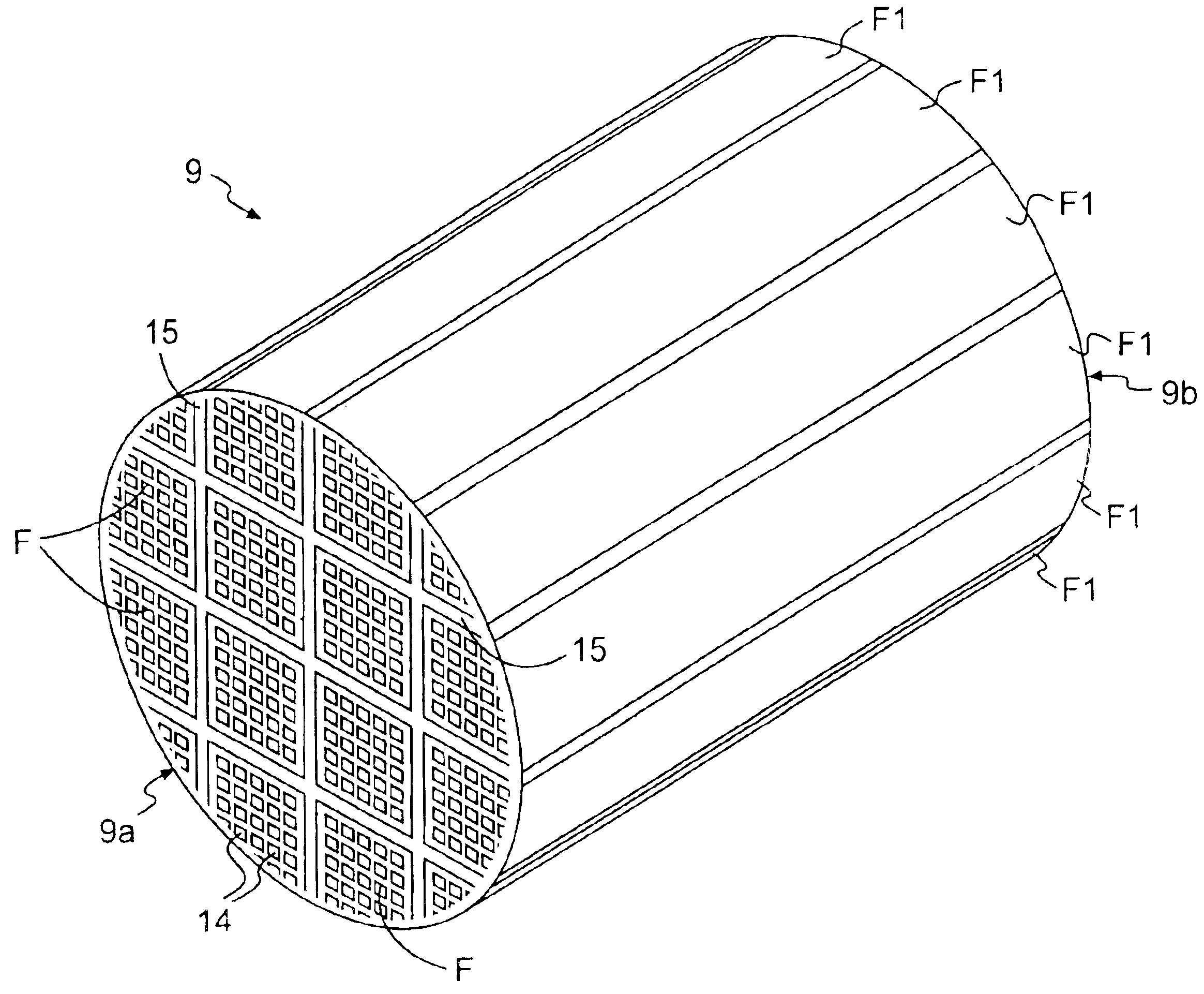
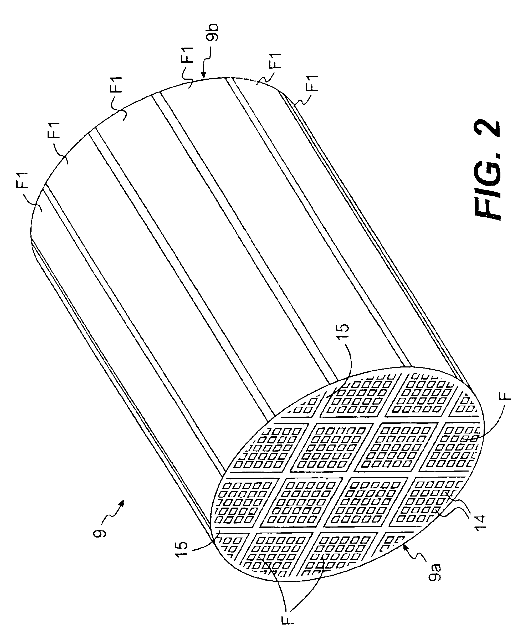
[0093](2) Then, after drying the molded product with a microwave dryer, the through holes 12 of the molded product was sealed by the sealing paste made of sint...

examples 1-2 , 1-3

EXAMPLES 1-2, 1-3

[0099]In example 1-2, the ceramic filter assembly 9 was prepared by setting the thickness t1 of the seal layer 15 at 1.0 mm. The other conditions were basically set in accordance with example 1-1. In example 3, the ceramic filter assembly 9 was formed by setting the thickness t1 of the seal layer 15 at 2.5 mm. The other conditions were basically set in accordance with example 1-1.

[0100]Then, the obtained two types of assemblies 9 were used for a certain period, and the cut surfaces were observed with the naked eye. The same desirable results as example 1-1 were obtained. Thus, it is apparent that the exhaust gas was efficiently processed in examples 1-2 and 1-3.

example 1-4

[0101]In example 1-4, the employed seal layer forming paste was prepared by mixing and kneading 25 wt % of a ceramic fiber (mullite fiber, shot content rate 5 wt %, fiber length 0.1 mm-100 mm), 30 wt % of silicon nitride powder having an average grain diameter of 1.0 μm, 7 wt % of alumina sol (the conversion amount of alumina sol being 20% serving as an inorganic binder, 0.5 wt % of poly vinyl alcohol serving as an organic binder, and 37.5 wt % of alcohol. The other portions were formed in accordance with example 1-1 to complete the ceramic filter assembly 9. The thickness t1 of the seal layer 15 was set at 1.0 mm. The thermal conductivity of the seal layer 15 was 0.2 W / mK.

[0102]Then, the obtained assembly 9 was used for a certain period, and the cut surfaces were observed with the naked eye. The same desirable results as example 1 were obtained. Thus, it is apparent that the exhaust gas was efficiently processed in example 4.


PUM

PropertyMeasurementUnit
thicknessaaaaaaaaaa
porosityaaaaaaaaaa
wt %aaaaaaaaaa

Abstract

A ceramic filter assembly having improved exhaust gas processing efficiency. The ceramic filter assembly (9) is produced by adhering with a ceramic seal layer (15) outer surfaces of a plurality of filters (F1), each of which is formed from a sintered porous ceramic body. The seal layer (15) has a thickness of 0.3 mm to 3 mm and a thermal conductance of 0.1 W / mK to 10 W / mk.

Description

[0001]This application is a continuation application of U.S. patent application Ser. No. 09 / 856,751 filed on Jul. 30, 2001, the entire contents of which are hereby incorporated by reference in their entirety, now U.S. Pat. No. 6,669,751 B1 issued Dec. 30, 2003, which is a 371 of PCT / JP00 / 066599, filed Sep. 26, 2000.TECHNICAL FIELD[0002]The present invention relates to a honeycomb filter and a ceramic filter assembly, and more particularly, to a honeycomb filter-formed from a sintered ceramic body and an integral ceramic filter assembly produced by adhering a plurality of honeycomb filters to one another.BACKGROUND ART[0003]The number of automobiles has increased drastically this century. As a result, the amount of gas discharged from automobile engines has continued to increase proportionally. Various substances suspended in the exhaust gas that is emitted, especially from diesel engines, cause pollution and severely affect the environment. Further, recently reported research result...

Claims


Application Information

Patent Timeline
Patent Type & Authority Patents(United States)
IPC IPC(8): B01D39/20B01D46/24B29C48/11B29C48/12C04B28/24C04B38/00F01N3/022F01N3/027
CPCB01D39/2075B01D46/2429B01D46/2448B01D46/2455B01D46/2462B01D46/2466B01D46/247B01D46/2474C04B28/24C04B38/008F01N3/0222B01D39/2086C04B37/005C04B35/6269C04B35/565C04B38/0009C04B38/0054C04B38/0074C04B41/5089C04B14/324C04B14/4656C04B24/383Y10T428/24149B01D46/2425B01D46/2444B01D46/2451B01D46/2459B01D2046/2433B01D2046/2437B01D2046/2477B01D2046/2481B01D2046/2488B01D2046/2492B01D2046/2496B01D2279/30C04B2111/00612C04B2111/00793F01N2260/10F01N2330/06F01N2330/14F01N2330/30F01N2450/28Y10S55/30Y10S264/48Y10S55/05C04B2235/5264C04B2235/5228C04B2235/5224C04B2235/383C04B2235/5436C04B2235/5445C04B2235/5472C04B2237/08C04B2237/083C04B2237/09C04B2237/365Y02T10/20B29C48/11B29C48/12Y02T10/12B01D46/2496B01D46/2486B01D46/2498B01D46/24492B01D46/24491B01D46/2478B01D46/2484B01D46/24494B01D46/2482B01D39/20
Inventor OHNO, KAZUSHIGESHIMATO, KOJITSUJI, MASAHIRO
Owner IBIDEN CO LTD
Why Eureka
Try Eureka