
Apparatus and method for continuous depyrogenation and production of sterile water for injection

a technology of pyrogenation and apparatus, which is applied in the direction of feed/discharge of settling tanks, water/sewage treatment by ion exchange, water/sewage treatment, etc., can solve the problems of system unsuitable for field use, pyrogens lose little of their potency, and swfi production is significant, etc., to achieve simple yet reliable process control system, reduce contact time for depyrogenation, and reduce the effect of pyrogenation

Inactive Publication Date: 2006-10-17
APPLIED RES ASSOCS INC
View PDF67 Cites 97 Cited by
  • Summary
  • Abstract
  • Description
  • Claims
  • Application Information

AI Technical Summary

Benefits of technology

[0026]The advantage of the present invention over the prior art is that the use of a combination of simple devices (e.g., flow restrictors, a pressure relief valve) produces a simple yet dependable process control system that obviates the need for expensive, bulky and complex sensors and valves. This allows the fluid processor to be compact but still reliable and effective. Also, the present invention allows for the continuous production of depyrogenated water rather than production by batches or semi-batches. Further, the present invention makes depyrogenation simpler and easier since HTP treatment does not leave any isolated pyrogen that would otherwise require periodic purging to remove. In addition, the present invention allows for depyrogenation at a high temperature. This results in a shorter contact time for depyrogenation and also simultaneously sterilizes the water. This eliminates the need for a separate sterilization stage such as passing water through sterilization filters. Moreover, high-temperature treatment is more reliable and effective than other approaches and is the sterilization method preferred by the FDA.
[0027]The fluid processor of the present invention is a compact, reliable, automated device having reduced energy requirements. It is designed to be easily deployable to remote locations where simplicity of operation, reliability, space, and energy requirements are critical for the continuous SWFI production from water. In addition, while the preferred embodiment of the present invention is directed to a fluid processor suitable for depyrogenation and the production of SWFI, the apparatus and method of the present invention may also find a broad range of applications in systems that have processing requirements similar to those of an SWFI fluid processor. Other objects, features, and advantages of the present invention will become apparent from the following detailed description of the best mode of practicing the invention when considered with reference to the drawings as follows:

Problems solved by technology

The production of SWFI is a significant problem for medical personnel operating under field conditions such as in combat or during disaster relief operations.
Pyrogens lose little of their potency over the years and effective depyrogenation requires high temperatures and long holding times.
However, distillation and RO systems only separate pyrogens from water.
This requirement makes these systems unsuitable for use under field conditions.
These systems also have other disadvantages that make them unsuitable for use in the field.
Distillation systems are generally highly energy intensive and require a number of system components such as heat exchangers, evaporators, condensers, and vapor compressors.
These components are either bulky or difficult to use or maintain in the field.
However, plate-and-frame heat exchangers do not comply with the heat exchanger design guidelines established by the FDA for continuous production of SWFI.
Moreover, RO filters are not entirely satisfactory.
In particular, RO systems lack a final heat sterilization capability that is currently required for approval by the FDA.
Such relatively low temperature systems present a problem because many objectionable micro-organisms that are good sources of endotoxins grow well in cold WFI.
The foregoing limitations make RO systems unsuitable for a SWFI production system to be used in the field.
However, these depyrogenating agents have to be removed from the water after completion of the depyrogenation process.
This makes this method more complicated and not easy to use in the field.
However, this method has the same disadvantage as apparatus that use distillation and RO methods in that the use of adsorbents only separates pyrogens from water.
However, Akcasu does not allow for the continuous production of depyrogenated water.
In addition to being unable to continuously produce depyrogenated water, the foregoing configuration of containers results in a fluid processor that is bulky and not suitable for use in the field.
However, the heating step requires a specially designed heat exchanger rather than a standard heat exchanger.
This makes the process more complicated and expensive.
Further, the oxidizing step requires exposing the heated water to a wet oxidation catalyst in a reactor with sufficient air or oxygen.
However, contacting water with the catalyst could result in the dissolution of certain components of the catalyst into the water being processed, and hence increasing the risk of contaminating the resulting product water.
This would increase the complexity of an SWFI production system to be used in the field.
Such apparatus are not satisfactory for field use since they require multiple steps to depyrogenate water or require frequent changing of filters to ensure depyrogenation.
This makes them more complicated and difficult to maintain in the field.
This makes it difficult to use these apparatus under field conditions where proper sanitizing equipment or facilities are not readily available.
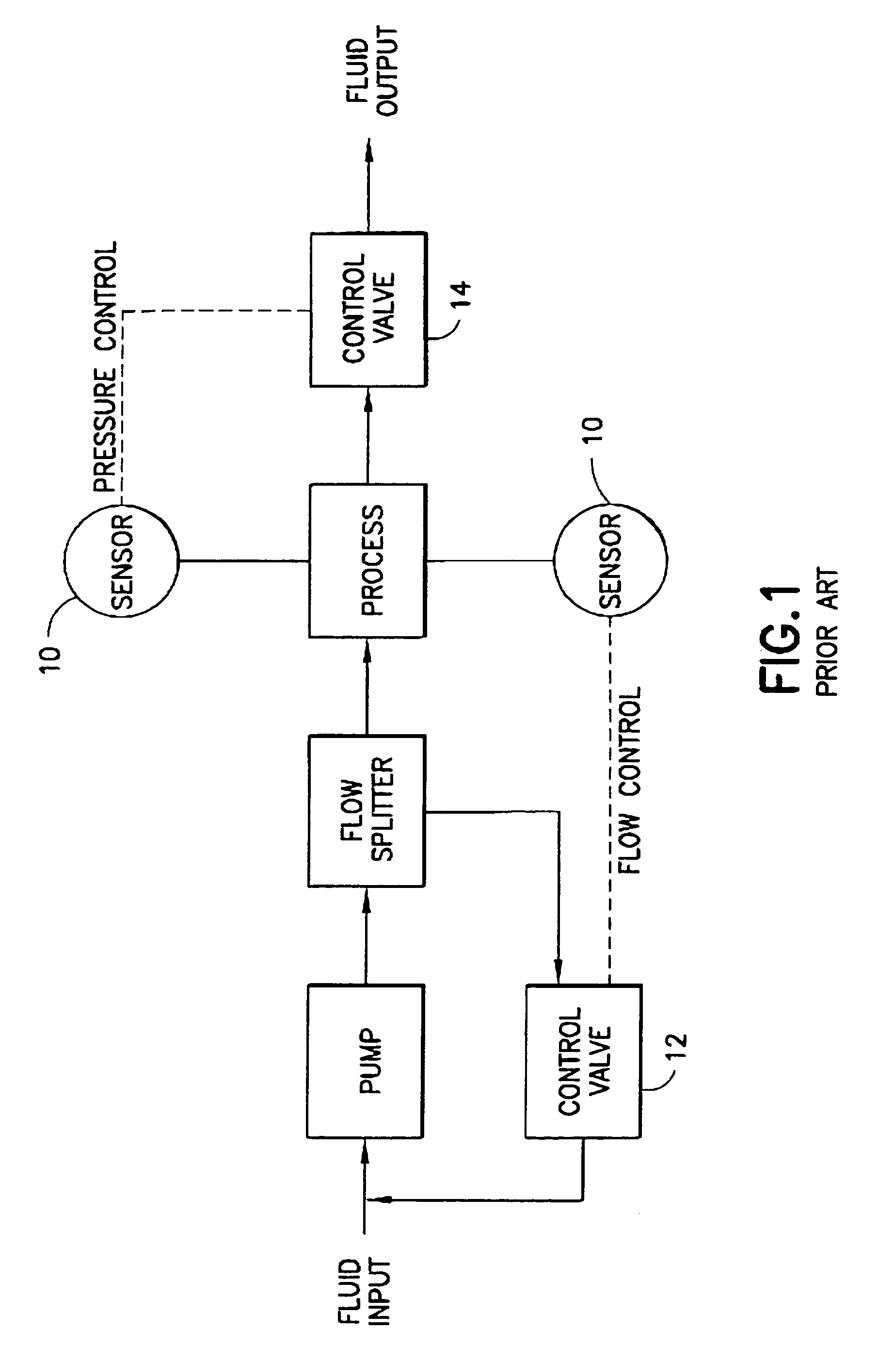
Automatic control valves are relatively bulky, complex, and prone to mechanical failure.
Thus, a system equipped with automatic control valves is not compact, robust, simple to operate or maintain.
In the second category are process control systems that use simple mechanisms but which are not precise or reliable and which require frequent adjustment.
This system often shows pressure fluctuation and / or drifting, and requires frequent adjustment of the pressure relief valve.

Method used


Image

  • Apparatus and method for continuous depyrogenation and production of sterile water for injection
  • Apparatus and method for continuous depyrogenation and production of sterile water for injection
  • Apparatus and method for continuous depyrogenation and production of sterile water for injection

Examples


Embodiment Construction

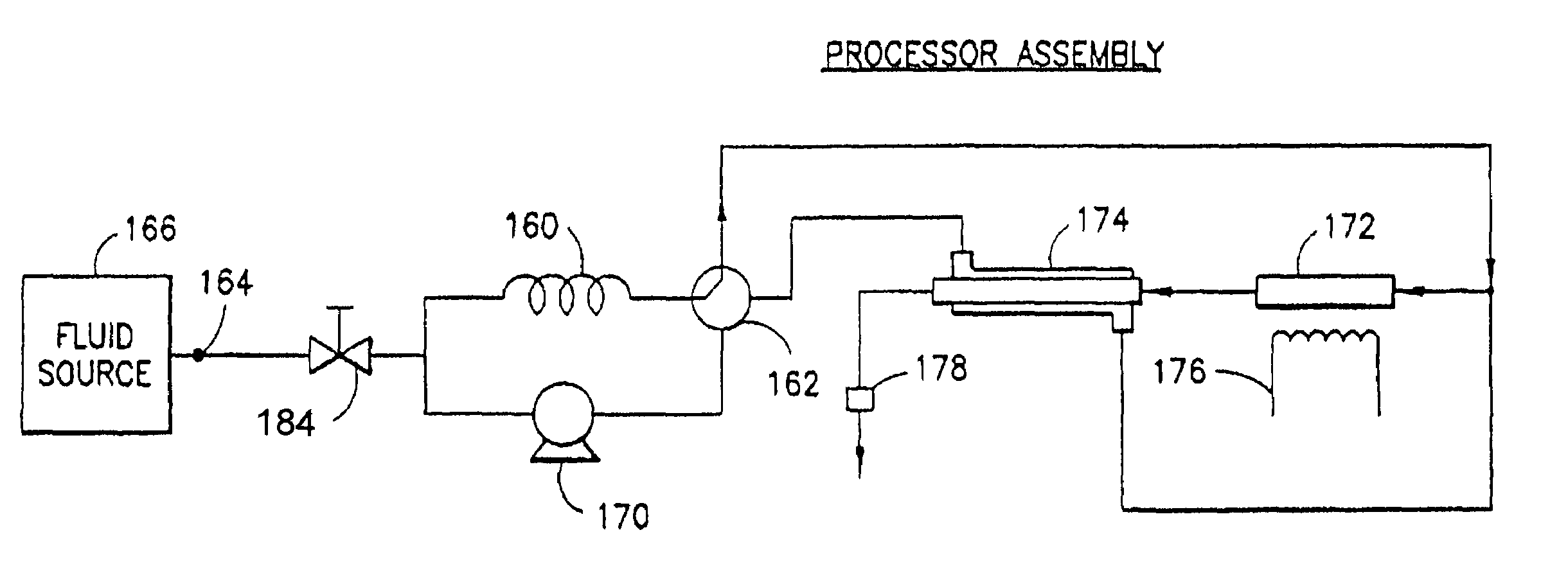
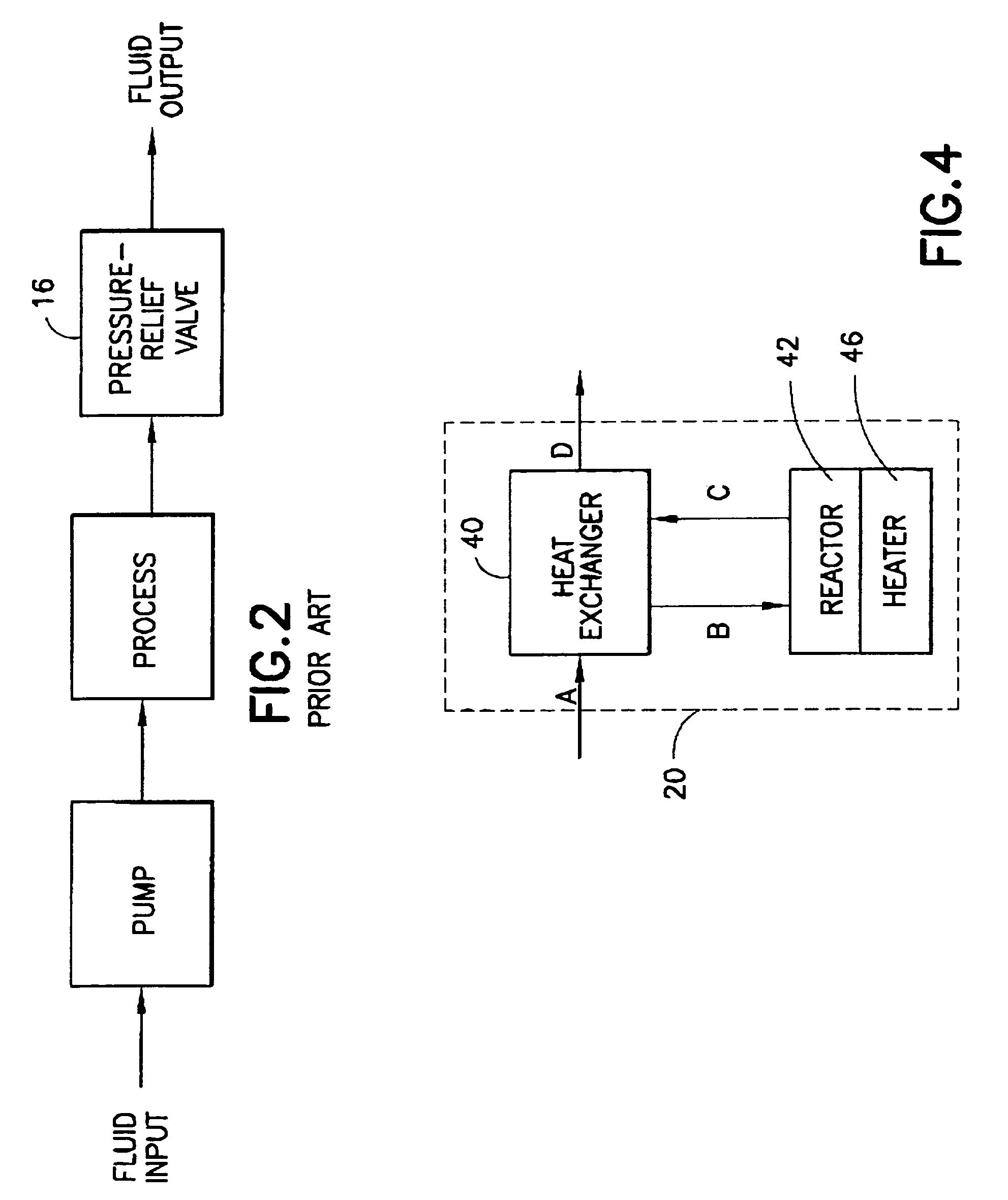
[0049]The apparatus and method of the present invention obtain a compact, reliable and easy to maintain and operate fluid processor having a low energy requirement that is suitable for depyrogenation and producing SWFI using HTP. A fluid processor in accordance with one embodiment of the present invention comprises a pump, a processor assembly, and a process control system comprising a flow splitter, a first and second flow restrictor, and a pressure relief valve. The process control system controls a fluid process by regulating the flow rate and pressure of the fluid within the fluid processor. Conduits (e.g., seamless tubing of stainless steel or other suitable alloys) transport the fluid between the different parts of the fluid processor. Brackets, clips or other devices commonly used in the industry hold components of the fluid processor in place.

[0050]The fluid processor is assembled from materials rated for the required temperature and pressure of the fluid process taking plac...


PUM

PropertyMeasurementUnit
Temperatureaaaaaaaaaa
Pressureaaaaaaaaaa
Lengthaaaaaaaaaa

Abstract

A fluid processor, suitable for the production of sterile water for injection, having a processor assembly and a process control system comprising a pump, a flow splitter, flow restrictors and a pressure relief valve. In a preferred embodiment, the processor assembly comprises a heat exchanger, a reactor and a heater arranged in a nested configuration. The preferred embodiment of the present invention also include a treatment assembly having a combination of filter, reverse osmosis and ion exchange devices and further incorporates an assembly and method allowing for the in situ sanitization of the fluid processor during cold start and shutdown to prevent bacteria growth during storage of the fluid processor. The fluid processor may include an electronic control system comprising a touch screen operator interface, a programmable logic controller and sensors for measuring temperature, pressure, flow rate, conductivity and endotoxin level.

Description

PRIORITY CLAIM[0001]This non-provisional application claims priority from United States Provisional Patent Application Ser. No. 60 / 395,377 filed on Jul. 12, 2002.[0002]The U.S. Government has a paid-up license in this invention and the right, in limited circumstances, to prepare the patent owner to license others on reasonable terms as provided for by the terms of contracts N00014-99-M-0254 and N00014-01-C-0101 awarded by the Office of Naval Research, United States Navy.FIELD OF THE INVENTION[0003]This invention generally relates to fluid processors, more particularly to a fluid processor having a process control system that uses an improved apparatus and method for process control and which is suitable for the depyrogenation and production of sterile water for injection using a hydrothermal process.BACKGROUND ART[0004]Sterile water for injection (SWFI) is an essential component in reconstituting freeze-dried blood products and in the preparation of “parenteral solutions” (i.e., sol...

Claims


Application Information

Patent Timeline
IPC IPC(8): C02F1/02A61L2/04C02F1/00C02F1/42C02F1/44C02F9/00F28D7/02
CPCA61L2/04C02F1/006C02F1/008C02F1/02C02F9/00F28D7/022C02F1/42C02F1/441C02F2103/026C02F2209/005C02F2209/03C02F2209/40C02F1/001C02F1/44Y10S210/90
Inventor LI, LIXIONGCAMPBELL, TIMOTHY J.NICHOLS, JR., ROBERT K.COZART, KRISTOPHER S.
Owner APPLIED RES ASSOCS INC
Learn More