

Positioning control apparatus and method capable of reducing relative position error without increasing gain and frequency band of transfer characteristics of control system
a technology of relative position error and control apparatus, which is applied in the direction of digital signal error detection/correction, instruments, recording signal processing, etc., can solve the problems of insufficient accuracy, inability to ensure sufficient accuracy, and inability to reduce relative position error in tracking the position, so as to reduce the relative position error
- Summary
- Abstract
- Description
- Claims
- Application Information
AI Technical Summary
Benefits of technology
Problems solved by technology
Method used
Image

Examples
first embodiment
[0056
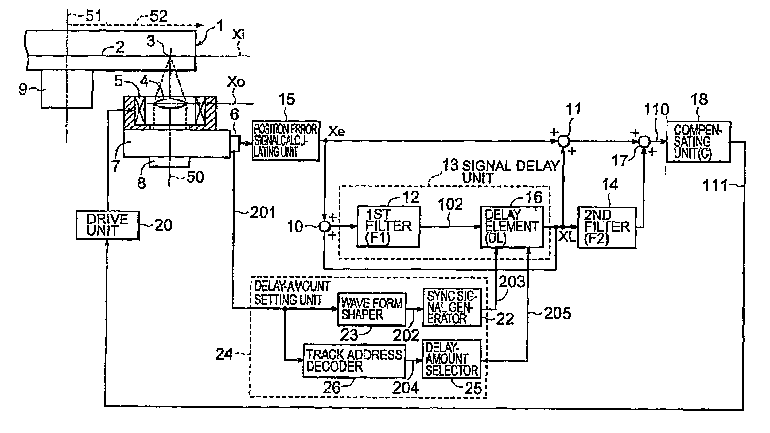
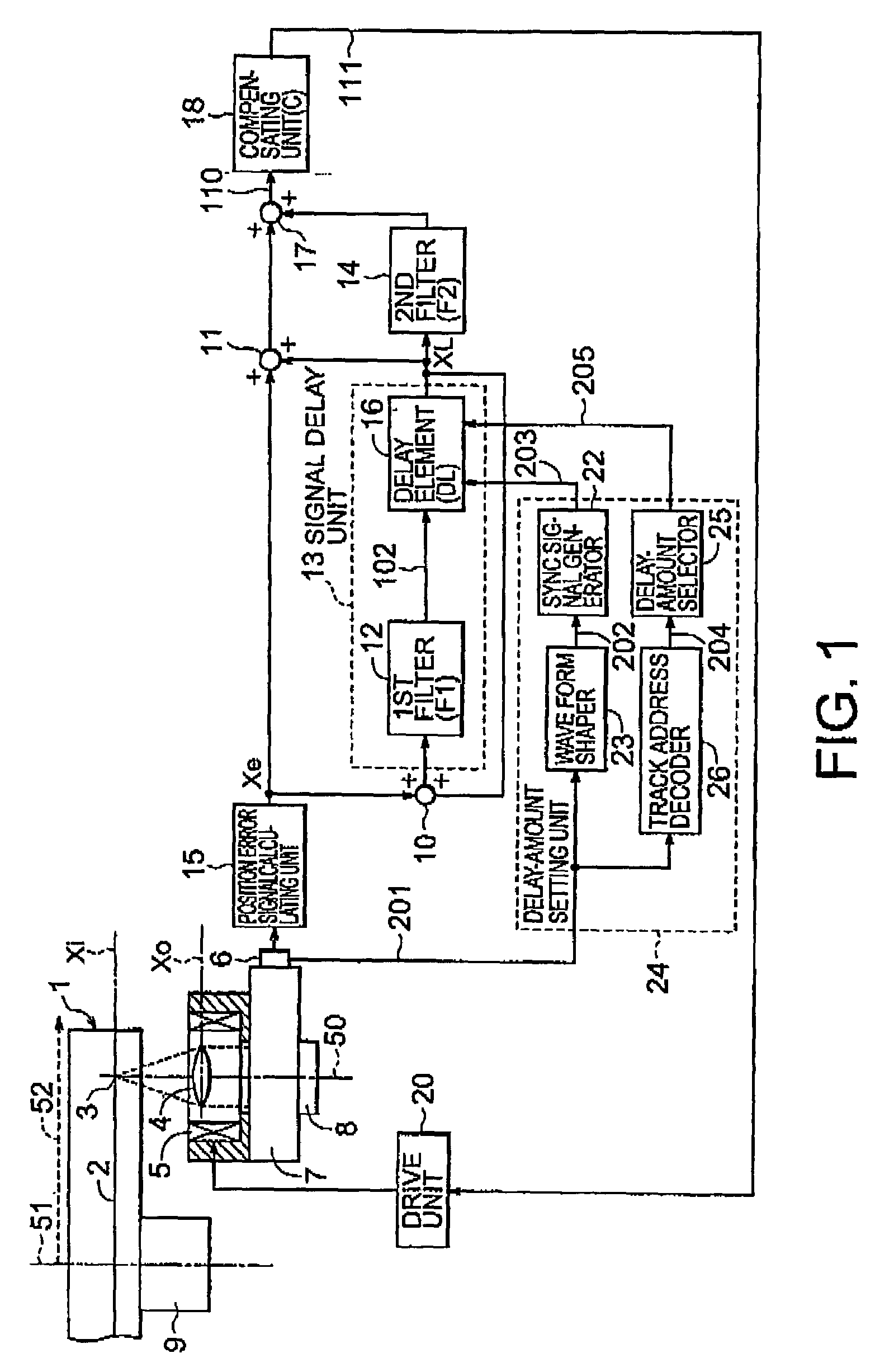
[0057]FIG. 1 is a block diagram showing the structure of an axial tracking (focus position control) apparatus in an optical disk apparatus according to a first embodiment of the present invention.
[0058]Referring to FIG. 1, a basic control unit comprises a moving member, a position detector, a compensating unit, and a drive unit, which are serially combined, and has a signal route from a signal 110 to a signal Xe.
[0059]Further, referring to FIG. 1, laser beams outputted from a laser source 8 are irradiated to an optical disk 1 through an optical head 7 and an objective lens 4. A laser beam spot 3 as a focus position of the laser beams is displaced by driving a focus actuator 5 an optical direction 50 of the laser beams (by the amount of movement Xo of the moving member).
[0060]According to the first embodiment, the moving member comprises the focus actuator 5 and the objective lens 4 which move the laser beam spot 3.
[0061]One spindle motor 9 rotates the optical disk 1 at almost a...
second embodiment
[0100
[0101]According to the first embodiment, the clock signal 203 and the data on the amount of signal delay 205 which are inputted to the delay element 16 in the signal delay unit 13 are set based on the reflected light signal from the optical disk 1. More simply, the same advantage can be obtained with the structure shown in FIG. 4 as an example. The difference between FIGS. 4 and 1 will be described.
[0102]A clock signal 101 with a fixed period, which is outputted from the clock generator 19, Is inputted to the delay element 16 and a counter circuit 28. A motor rotational phase detecting signal (FG signal) 301 which is detected by a hole element 27 incorporated in a three-phase blushless motor used as the spindle motor 9 and formed into 2 values by a comparator circuit (not shown) is inputted into the counter circuit 28. The counter circuit 28 counts the number of clocks of the clock signal 101 corresponding to one period of the rotation of the optical disk 1 based on the FG sign...
third embodiment
[0110
[0111]FIG. 6 is a block diagram showing the structure of a positioning control apparatus according to a third embodiment of the present invention.
[0112]The delay-amount setting unit comprises the waveform shaper 23, the synchronous signal generator 22, the track address decoder 26, and the delay-amount selector 25 according to the first embodiment.
[0113]As a feature according to the third embodiment, referring to FIG. 6, a delay-amount setting unit comprises an upper controller 38 which perform the operation for controlling the rotation of the spindle motor 9 and the operation for recording and reading information in an optical disk apparatus, the spindle motor 9, and the hole element 27.
[0114]The upper controller 38 comprises the waveform shaper 23, the synchronous signal generator 22, the track address decoder 26, the delay-amount selector 25, a spindle motor control unit 37, and a reference signal generator 32. The spindle motor control unit 37 comprises a speed error calcul...
PUM
 Abstract
Description
Claims
Application Information