Transmission circuit

a transmitter circuit and circuit technology, applied in the direction of digital transmission, modulation, pulse technique, etc., can solve the problems of incorrect restoration of modulated signal wave, known eer technique, etc., to prevent signal deterioration, high efficiency, and without signal deterioration

Inactive Publication Date: 2006-11-21
COLLABO INNOVATIONS INC
View PDF9 Cites 40 Cited by
  • Summary
  • Abstract
  • Description
  • Claims
  • Application Information

AI Technical Summary

Benefits of technology

[0017]The inventive transmission circuit may further include frequency converting means disposed between the first selection outputting means and the RF power amplifier. Then, it is possible to process an RF signal covering a wider band. For example, since the DA converter handles signals with frequencies in the band of several hundreds MHz at most, the DA converter cannot process carriers whose frequencies exceed GHz. However, if the frequency converting means such as a quadrature converter is used, the carrier frequency is up-converted easily.
[0018]In addition to the basic configuration described above, the inventive transmission circuit may include selection outputting means for outputting a constant voltage to the constant-voltage supply line if the amplitude value of the amplitude component is smaller than or equal to the threshold value and outputting the amplitude component to the amplitude component line if the amplitude value is larger than the threshold value, depending on the judgment result of the judging means. Then, a pseudo-EER technique which is substantially the same as an EER techniq...

Problems solved by technology

However, the known EER technique has a drawback in which the modulated signal wave is not restored correctly because the resultant spectrum mask or EVM (Error Vector Magnitu...

Method used


Image

  • Transmission circuit
  • Transmission circuit
  • Transmission circuit

Examples


embodiment 1

[0029]Hereinafter, a first embodiment of the present invention will be described with reference to the drawings. In this embodiment, OFDM is adopted for a modulation scheme. Examples of systems using OFDM are based on IEEE 802.11a standard, one of the wireless LAN standards. In a wireless LAN system, each of the 52 orthogonal subcarriers is modulated by, for example, 64 QAM, then an inverse discrete Fourier transform is conducted, and then each resultant carrier is multiplexed, thus obtaining an OFDM modulated signal. The 52 carriers are separated with a spacing of 312.5 kHz and occupy 52×312.5=16.25 MHz in total.

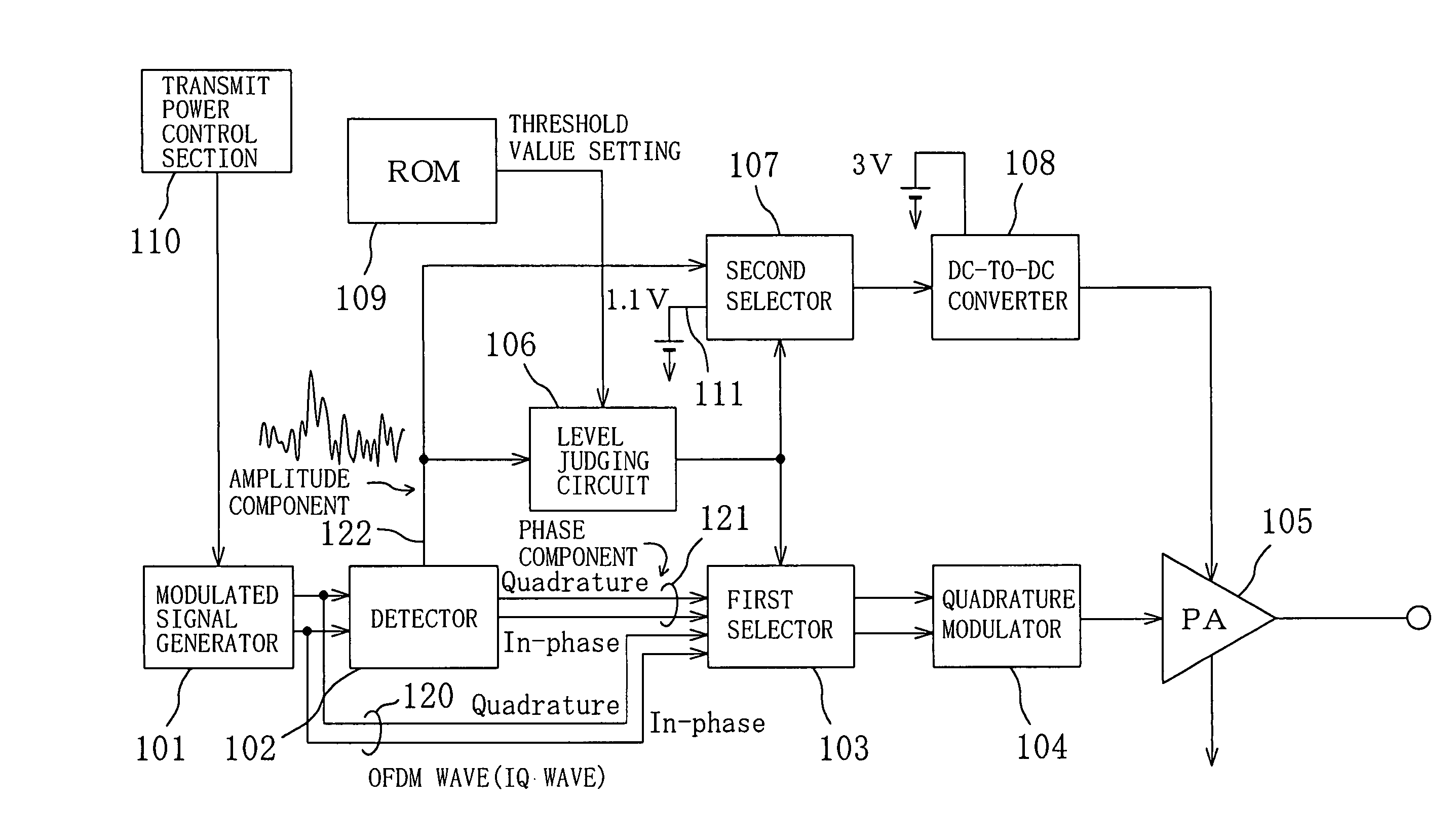
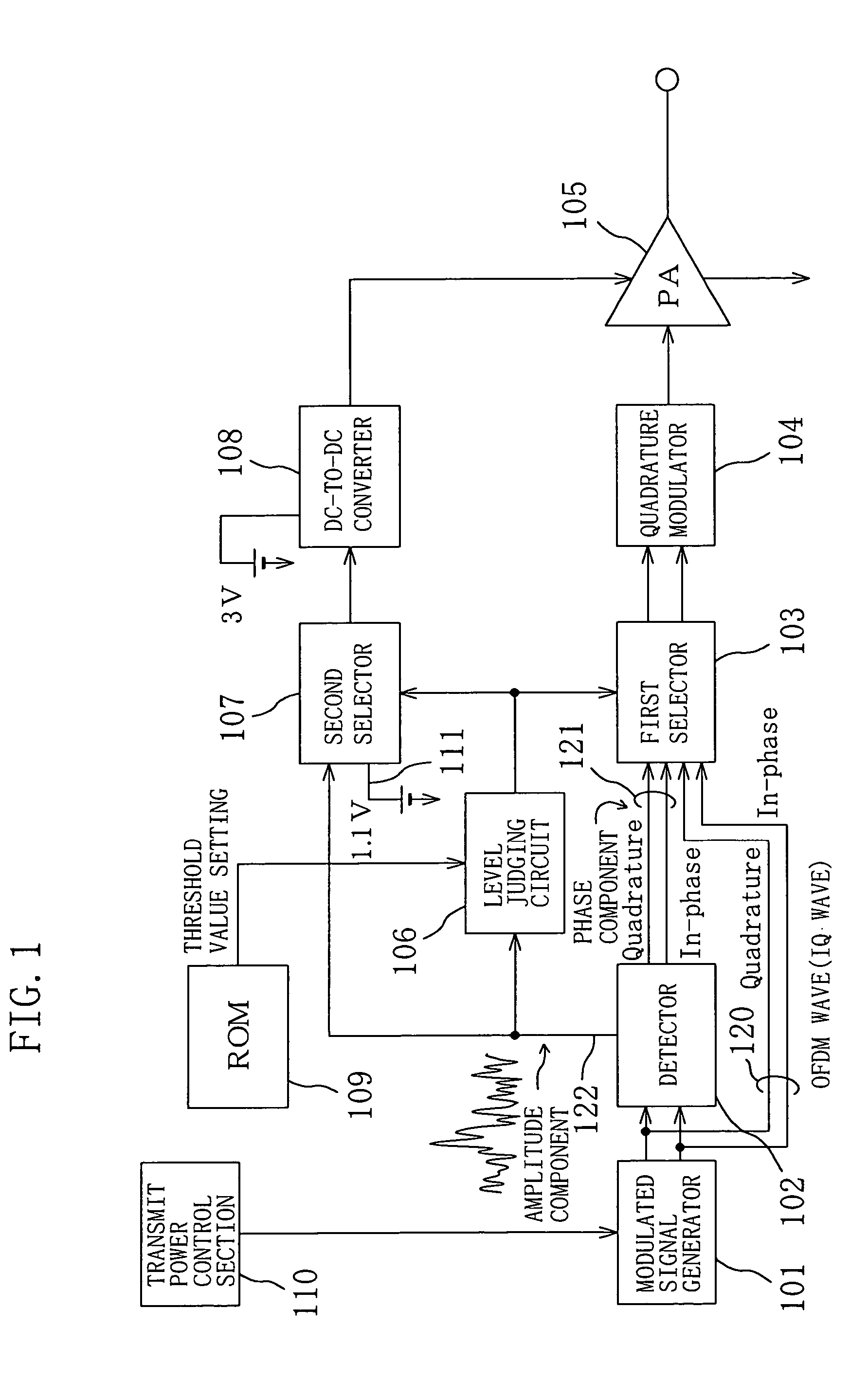
[0030]FIG. 1 is a circuit diagram showing a transmission circuit for implementing an EER technique according to the first embodiment. As shown in FIG. 1, the transmission circuit includes: a modulated signal generator 101 as a modulated signal generating means for generating an OFDM modulated wave (modulated signal) including an amplitude component and a phase component; mo...

embodiment 2

[0050]In this embodiment, OFDM is also adopted for modulation. FIG. 4 is a circuit block diagram schematically showing a configuration of a transmission circuit according to a second embodiment of the present invention. As shown in FIG. 4, the transmission circuit includes: a modulated signal generator 201 as a modulated signal generating means for generating an OFDM modulated wave (modulated signal) including an amplitude component and a phase component; modulated signal lines 220 through which the OFDM modulated wave flows; a detector 202 as a modulated signal detecting signal for detecting the amplitude component and the phase component of the OFDM modulated wave; an amplitude component line 222 for transmitting the amplitude component of the OFDM modulated wave; a level judging circuit 206 as a judging means for judging whether the level of the amplitude is higher than a threshold voltage level or not; a ROM 209 as a storage means for storing a threshold voltage to be used as a ...

modified example of embodiment 2

[0078]FIG. 5 is a circuit block diagram schematically showing a configuration of a transmission circuit according to a modified example of the second embodiment. As in the transmission circuit of the second embodiment shown in FIG. 4, the transmission circuit of this modified example also includes: a modulated signal generator 201; a detector 202; a quadrature modulator 204; a PA 205; modulated signal lines 220; and an amplitude component line 222. Basic functions of these circuit elements are the same as those described in the second embodiment.

[0079]In this modified example, one DC-to-DC converter 211 is provided and a selector 207 in which a DA converter is incorporated is interposed between the detector 202 and the DC-to-DC converter 211. A threshold voltage level of 1.1 V stored in a ROM 209 as a storage means is supplied to an RF input terminal of the selector 207 through a constant-voltage supply line 251. Specifically, in this modified example, the threshold voltage level to...


PUM


Abstract

A transmission circuit includes: a modulated signal generator; a modulated signal line where an OFDM modulated wave flows; a detector; a phase component line for transmitting a phase component; an amplitude component line for transmitting an amplitude component; a level judging circuit for judging the level of the amplitude component; a constant-voltage supply line; first and second selectors; a quadrature converter; and an RF power amplifier. An EER or pseudo-EER technique is performed in a region where the RF input-output characteristic of the RF power amplifier with an EER technique exhibits a linear response, whereas usual modulation is performed in a region where a nonlinear response is exhibited. The modulation method is switched using the level judging circuit and the selectors with reference to a threshold value which is the boundary between the region where the linear response is exhibited and the region where the nonlinear response is exhibited.

Description

BACKGROUND OF THE INVENTION[0001]The present invention relates to circuits for transmitters of radio communications, below denoted as “transmission circuits”.[0002]In general, to process modulated signals with amplitude modulation, especially multiple modulation such as Quadrature Amplitude Modulation (QAM), radio-frequency power amplifiers in transmission circuits for transmitting power to antennas need linear amplification. Therefore, class A or AB had been adopted as operation classes of the RF power amplifiers.[0003]However, with the progress of broadband communication, communication methods using subcarrier modulation such as Orthogonal Frequency Division Multiplex (OFDM) have come to be used and high efficiency is not expected any more with the conventional class-A or AB radio frequency amplifiers. That is, in the OFDM modulation, subcarriers are overlapped so that a large amount of power is instantaneously generated at random time and the ratio between the average power and t...

Claims


Application Information

Patent Timeline
IPC IPC(8): H04B1/02H03F1/02H04B1/04
CPCH03F1/0227H04B1/0475
Inventor TANABE, MITSURUTANAKA, KOICHIRO
Owner COLLABO INNOVATIONS INC
Why Eureka
Try Eureka