Hydrogen separation membrane, hydrogen separation unit, and manufacturing method for hydrogen separation membrane

a technology of hydrogen separation membrane and manufacturing method, which is applied in the direction of membranes, separation processes, colloidal chemistry, etc., can solve the problems of large danger of defects pinhole-shaped defects, and unnecessary increase of membrane thickness, so as to reduce the thickness of hydrogen separation membrane and prevent defects from penetrating in the thickness direction

Inactive Publication Date: 2006-12-05
MITSUBISHI HEAVY IND LTD
View PDF29 Cites 8 Cited by
  • Summary
  • Abstract
  • Description
  • Claims
  • Application Information

AI Technical Summary

Benefits of technology

[0023]According to the manufacturing method for a hydrogen separation membrane in accordance with the present invention, the thickness of the hydrogen separation membrane is decreased by scraping off the foil, so that defect holes

Problems solved by technology

However, in the case where a method for obtaining a hydrogen separation membrane by vapor deposition or plating is used, pores in the porous support must be closed by the deposition of a film, which necessarily increases the membrane thickness.
If it is attempted to decrease the membrane thickness, a portion of porous support in which relatively large pores are formed cannot be closed completely, which may cause pinhole-shaped defects.
Therefore, if it is attempted to decrease the membrane thickness only by rolling, there is a great danger of causing defects penetrating in the thickness direction.
However, in the case where a method for obtaining a uniformly thin hyd

Method used


Image

  • Hydrogen separation membrane, hydrogen separation unit, and manufacturing method for hydrogen separation membrane
  • Hydrogen separation membrane, hydrogen separation unit, and manufacturing method for hydrogen separation membrane
  • Hydrogen separation membrane, hydrogen separation unit, and manufacturing method for hydrogen separation membrane

Examples


first embodiment

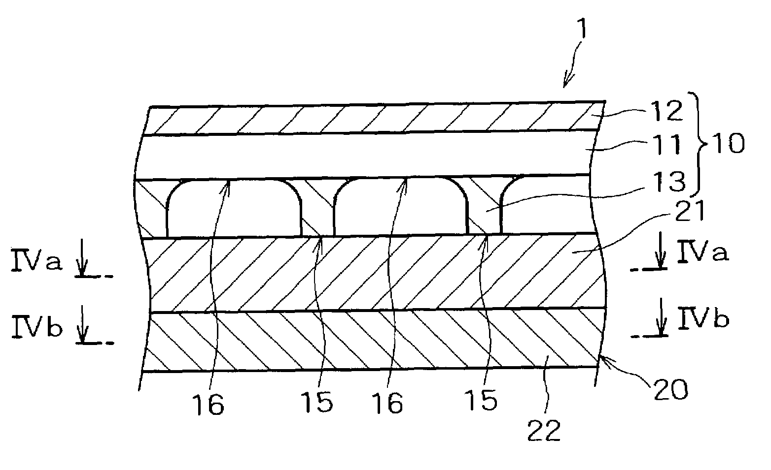
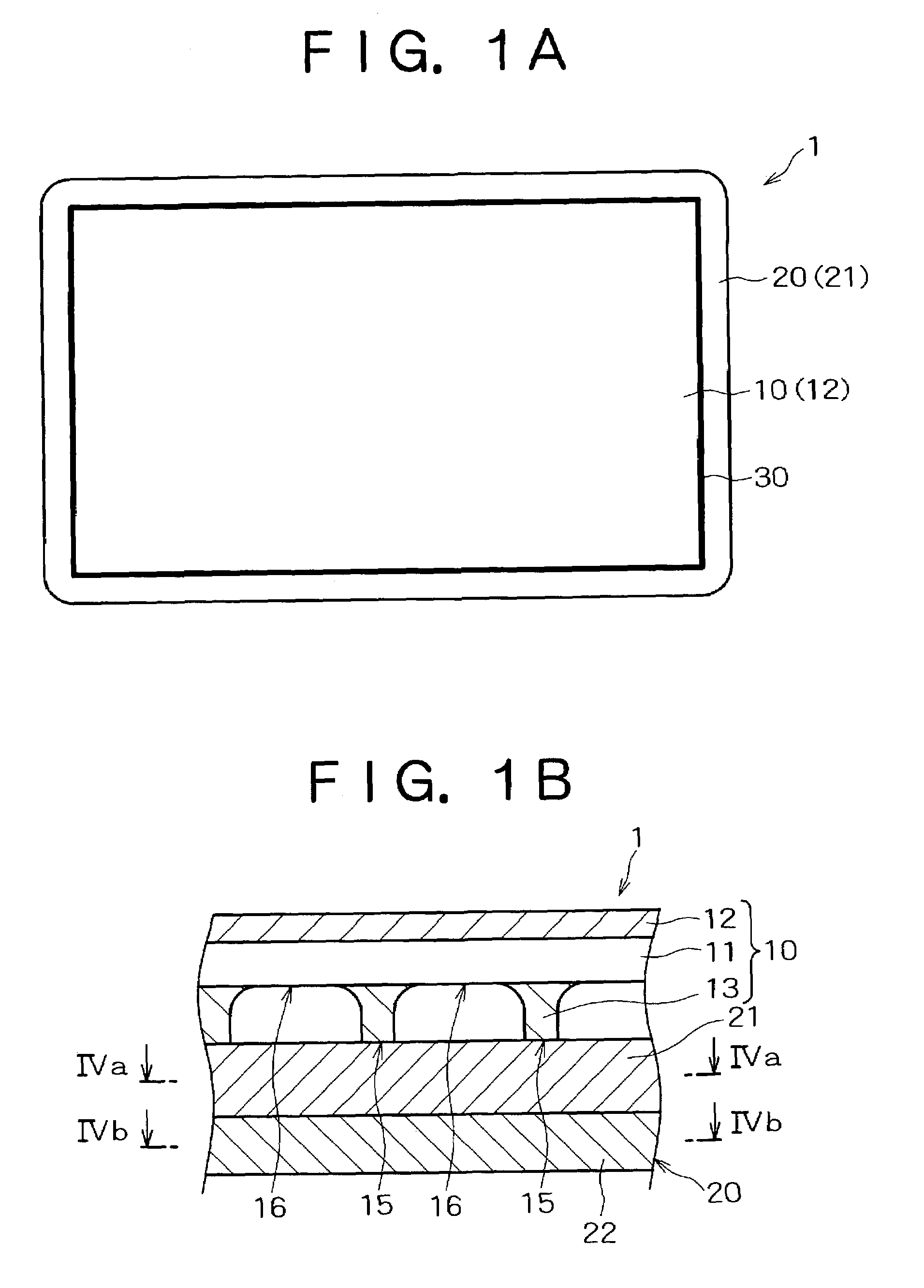
[0037]FIG. 1 is a view of a hydrogen separation unit 1 in accordance with a first embodiment to which the present invention is applied, in which FIG. 1(a) is a front view taken from the side in contact with a mixed gas used as a source gas, and FIG. 1(b) is a side view of FIG. 1(a).

[0038]In this embodiment, the hydrogen separation unit 1 has a hydrogen separation membrane 10 of a comb shape in cross section and a metallic porous support sheet 20 (support) to which the hydrogen separation membrane 10 is attached.

[0039]In this embodiment, as shown in FIGS. 1 and 2, the hydrogen separation membrane 10 includes a core material 11 consisting of an alloy of Pd and rare-earth element, a surface material 12 (oxidation resistant layer) consisting of a Pd—Ag alloy, which is provided on the side in contact with the mixed gas so as to cover the core material 11, and a surface material 13 consisting of a Pd—Ag alloy, which is formed into a bridge girder shape in cross section beneath the core ma...

second embodiment

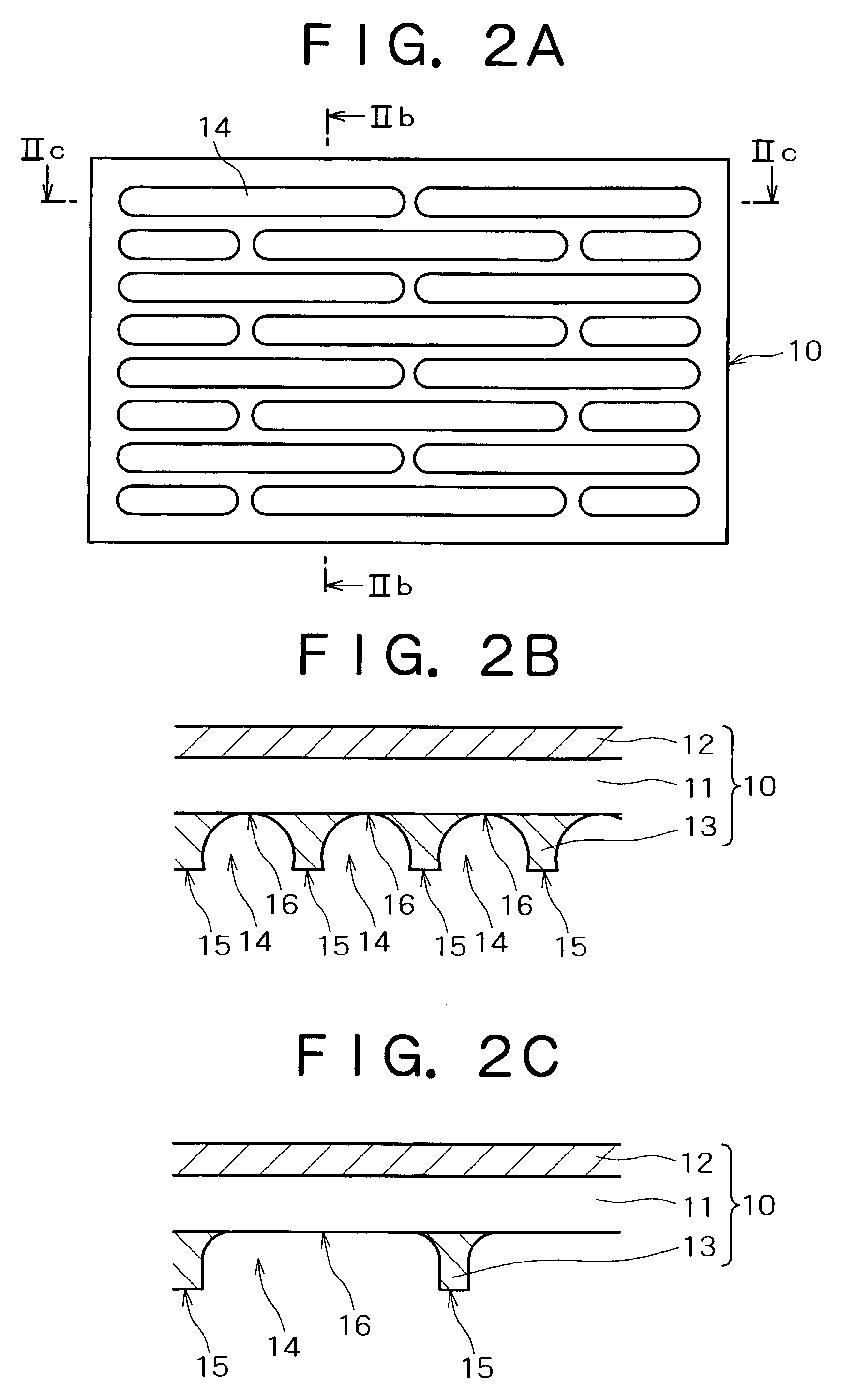
[0073]FIG. 7 shows the hydrogen separation membrane 10 of the hydrogen separation unit 1 in accordance with a second embodiment to which the present invention is applied. FIG. 7(a) is a front view of the hydrogen separation membrane 10, and FIG. 7(b) is a sectional view taken along the line VIIb—VIIb of FIG. 7(a). The hydrogen separation membrane 10 of this embodiment is almost the same as that described in the first embodiment except that the shape of the pit 14 is circular and the pits 14 are arranged in a zigzag form.

[0074]In this embodiment, as shown in FIGS. 8(a) and 8(c), the diameter d of the pit 14 is appropriately selected from the range of 10 to 500 m, and the clearance e between the adjacent pits 14 from the range of 2 to 50 μm. Also, as shown in FIGS. 8(b) and 8(c), the thickness t1 of the hydrogen separation membrane 10 corresponding to a portion in which the pit 14 is formed is appropriately selected from the range of 2 to 20 μm, and the thickness t2 of the hydrogen se...


PUM


Abstract

There is provided a hydrogen separation membrane capable of providing high hydrogen permeability and accommodating an increase in pressure difference, a hydrogen separation unit, and a manufacturing method for a hydrogen separation membrane. The hydrogen separation unit 1 has a hydrogen separation membrane 10 and a metallic porous support sheet 20 attached to the hydrogen separation membrane 10. By forming a plurality of pits in the surface of the hydrogen separation membrane 10, a thick-wall portion 15 having a large thickness and a thin-wall portion 16 having a small thickness are provided on the hydrogen separation membrane 10. Also, as a method for forming pits i.e. thin-wall portions 16, etching process is used.

Description

RELATED APPLICATION[0001]This application claims priority from Japanese Patent Application No. 2002-167414 filed Jun. 7, 2002, the disclosure of which is incorporated by reference herein in its entirety.FIELD OF THE INVENTION[0002]The present invention relates to a hydrogen separation membrane used for separating hydrogen gas from a mixed gas, a hydrogen separation unit, and a manufacturing method for a hydrogen separation membrane. More particularly, it relates to a hydrogen separation membrane having both high hydrogen permeability and high mechanical strength, a hydrogen separation unit, and a manufacturing method for a hydrogen separation membrane.BACKGROUND OF THE INVENTION[0003]The principle of manufacturing high purity hydrogen by using a hydrogen separation membrane is that a source gas (containing hydrogen) having a higher pressure than that of high purity hydrogen to be obtained is brought into contact with a hydrogen separation membrane using hydrogen permeable metallic f...

Claims


Application Information

Patent Timeline
IPC IPC(8): B01D53/22B01D71/02B01D69/00B01D69/10B01D69/12C01B3/50C01B3/56
CPCB01D53/22B01D63/087B01D67/0069B01D67/0072B01D69/00B01D69/10B01D71/022C01B3/505B01D2257/108B01D2313/42C01B2203/0405Y10S55/05B01D2325/04B01D2325/08B01D2325/24B01D2325/30B01D69/106B01D69/108B01D71/02231
Inventor TAKATANI, HIDEAKIKOBAYASHI, TOSHIROKAWANO, MASAKIKOBAYASHI, KAZUTO
Owner MITSUBISHI HEAVY IND LTD
Why Eureka
Try Eureka