High speed Ge channel heterostructures for field effect devices

a field effect device and heterostructure technology, applied in the field of silicon germanium based materials systems, can solve the problems of no measurement or data published subsequently of ge properties or ge layered structures, and achieve the effect of high electron and hole mobilities and high mobilities

Inactive Publication Date: 2006-12-05
ELPIS TECH INC
View PDF7 Cites 126 Cited by
  • Summary
  • Abstract
  • Description
  • Claims
  • Application Information

AI Technical Summary

Benefits of technology

[0016]It is an object of the invention to provide a layered structure which allows for p-channel field effect transistors to be formed having a channel with extremely high hole mobility.
[0018]It is a further object of the invention to provide p-channel devices where the channel structure takes advantage of the higher compressive strain with the benefits of a higher barrier or a deeper confining channel for hole carriers as compared to a replacement channel using a single SiGe layer.
[0020]It is a further object of the invention to provide a hole mobility of greater than 1,000 cm2 / Vs in an optimum p-channel structure composed of a strained Ge layer of 100–200 Å thick to produce the highest hole mobility in the SiGe materials system.
[0024]It is a further object of the invention to provide a near surface channel device where the active Ge channel has high electron and hole mobilities and may be operated in the enhancement mode.
[0025]It is a further object of the invention to provide a near surface channel device where the active Ge channel is suitable for making complementary MOSFET devices having high mobilities.
[0026]It is a further object of the invention to provide a layered structure and scheme where a desired relaxed Si1-xGex layer can be better achieved by the addition of a single over shoot layer (when x≦0.5) or a double overshoot (when x>0.5) in the grade-up composition of the SiGe buffer structure.

Problems solved by technology

However, no measurements or data have been subsequently published of Ge properties or Ge layered structures with mobilities over 2000 cm2 / Vs at room temperature.

Method used


Image

  • High speed Ge channel heterostructures for field effect devices
  • High speed Ge channel heterostructures for field effect devices
  • High speed Ge channel heterostructures for field effect devices

Examples


Embodiment Construction

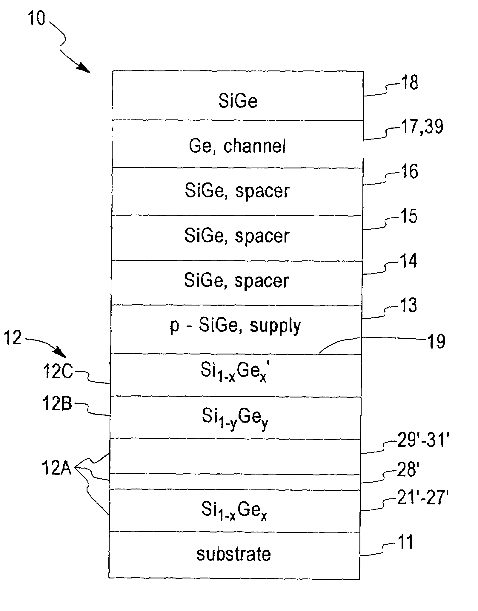
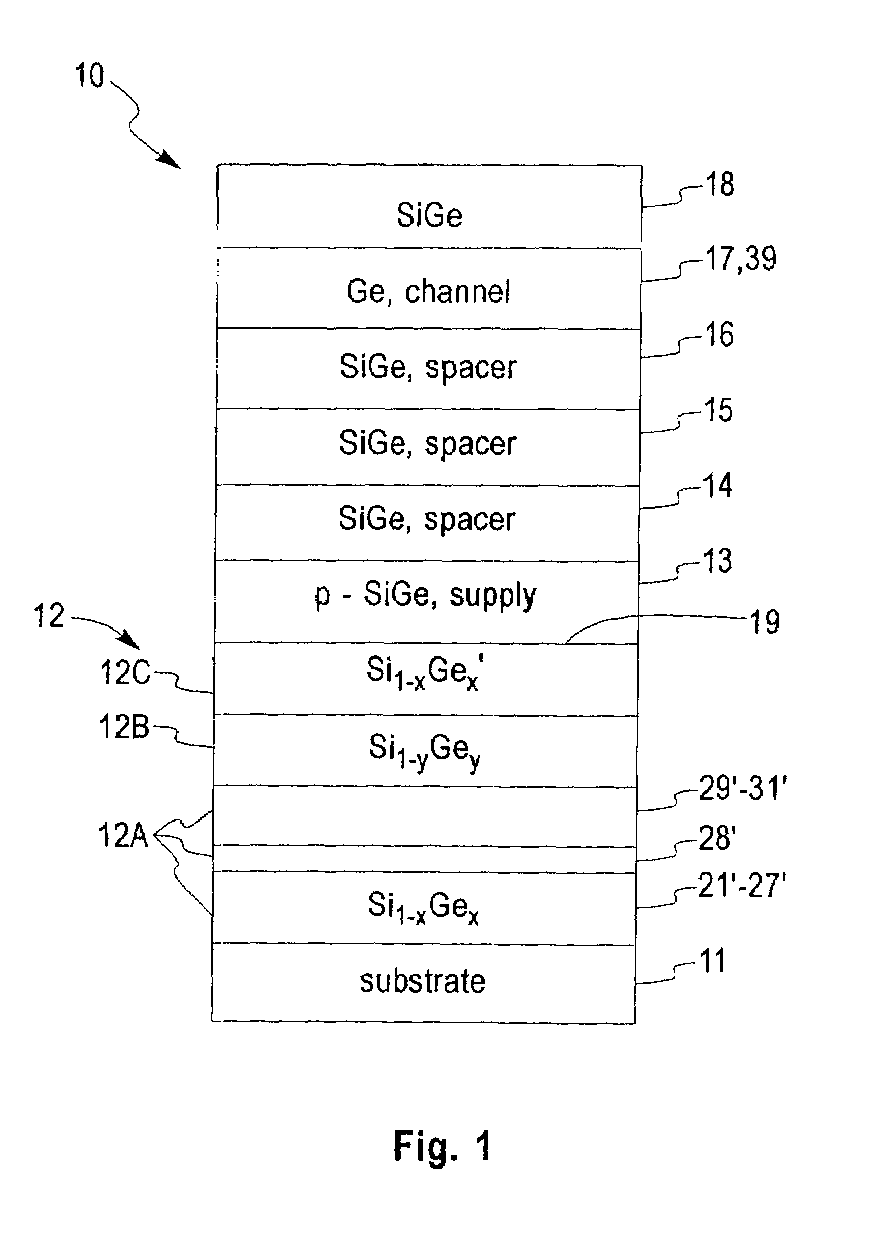
[0045]Referring to the drawing, and in particular to FIG. 1, a cross section view of a layered structure 10 for a Ge p-channel modulation-doped SiGe heterostructure is shown to illustrate the embodiment of the invention. Layers 12–18 are epitaxially grown on a single crystal semiconductor substrate 11 which may be Si, SiGe, Ge, SiC, GaAs, silicon-on-sapphire (SOS), silicon-on-insulator (SOI), Bond and Etch back Silicon On Insulator (BESOI), etc. using an epitaxial growth technique such as ultra high vacuum chemical vapor deposition (UHV-CVD), molecular beam epitaxy (MBE), or rapid thermal chemical vapor deposition (RTCVD). For a description of UHV-CVD methods for growing epitaxial Si and Si1-xGex films on a silicon substrate, reference is made to U.S. Pat. No. 5,298,452 by B. S. Meyerson which issued Mar. 29, 1994 entitled “Method and Apparatus for Low Temperature, Low Pressure Chemical Vapor Deposition of Epitaxial Silicon Layers” which is incorporated herein by reference.

[0046]An ...


PUM


Abstract

A method and a layered heterostructure for forming high mobility Ge channel field effect transistors is described incorporating a plurality of semiconductor layers on a semiconductor substrate, and a channel structure of a compressively strained epitaxial Ge layer having a higher barrier or a deeper confining quantum well and having extremely high hole mobility for complementary MODFETs and MOSFETs. The invention overcomes the problem of a limited hole mobility due to alloy scattering for a p-channel device with only a single compressively strained SiGe channel layer. This invention further provides improvements in mobility and transconductance over deep submicron state-of-the art Si pMOSFETs in addition to having a broad temperature operation regime from above room temperature (425 K) down to cryogenic low temperatures (0.4 K) where at low temperatures even high device performances are achievable.

Description

CROSS REFERENCE TO RELATED APPLICATION[0001]This application is cross referenced to Ser. No. 09 / 267,323 filed Mar. 12, 1999 by Jack O. Chu et al. entitled “High Speed Composite p-channel Si / SiGe Heterostructure for Field Effect Devices” which describes a field effect transistor with a channel having a composite layer of a layer of Ge and a layer of SiGe both under compression to obtain higher mobility which is incorporated herein by reference.FIELD OF THE INVENTION[0002]This invention relates to a silicon and silicon germanium based materials system and more specifically, to a novel epitaxial field effect transistor structure useful for high-speed low-noise, microwave, submillimeter-wave and millimeter-wave applications. Preferably, the epitaxial field effect transistor structure includes a high performance Ge channel in a structure incorporating silicon and silicon germanium layers to form CMOS devices or circuits, high electron mobility transistors (HEMT's), and modulation-doped h...

Claims


Application Information

Patent Timeline
Patent Type & Authority Patents(United States)
IPC IPC(8): H01L29/06H01L21/44H01L31/0336H01L31/072
CPCH01L21/823807H01L27/092H01L29/1054H01L29/66431H01L29/7782
Inventor CHU, JACK OON
Owner ELPIS TECH INC
Why Eureka
Try Eureka