Humidifier for fuel cell using high conductivity carbon foam

a high-conductivity carbon foam and fuel cell technology, applied in the direction of ceramicware, lighting and heating apparatus, separation processes, etc., can solve the problems of high loss, dramatic medium chill, high loss, etc., and achieve high conductivity, efficient heat transfer, and more surface area

Inactive Publication Date: 2006-12-12
UT BATTELLE LLC
View PDF103 Cites 18 Cited by
  • Summary
  • Abstract
  • Description
  • Claims
  • Application Information

AI Technical Summary

Benefits of technology

[0006]This invention overcomes the problems associated with traditional humidification techniques by utilizing the graphite foam to act as both a water management material as well as a heat management device. By using the high conductivity of the foam ligaments, the foam can efficiently transfer heat from a hot source to the water on the surface of the ligaments to effect the evaporation and, thus humidification. More importantly, the advantage of significantly more surface area for this evaporation than traditional devices, will allow a smaller humidifier as well as the ability to capture waste heat to drive the humidification.
[0007]The invention comprises a method and apparatus of supplying humidified air to a device or process.

Problems solved by technology

However, the drawbacks to these conventional methods are that the evaporation of the water from the evaporating medium produces an endothermic effect and the medium chills dramatically, albeit very slowly due to its low conductivity.
Attempts to overcome this by heating the evaporative medium have been unsuccessful since the trad

Method used


Image

  • Humidifier for fuel cell using high conductivity carbon foam
  • Humidifier for fuel cell using high conductivity carbon foam
  • Humidifier for fuel cell using high conductivity carbon foam

Examples


first embodiment

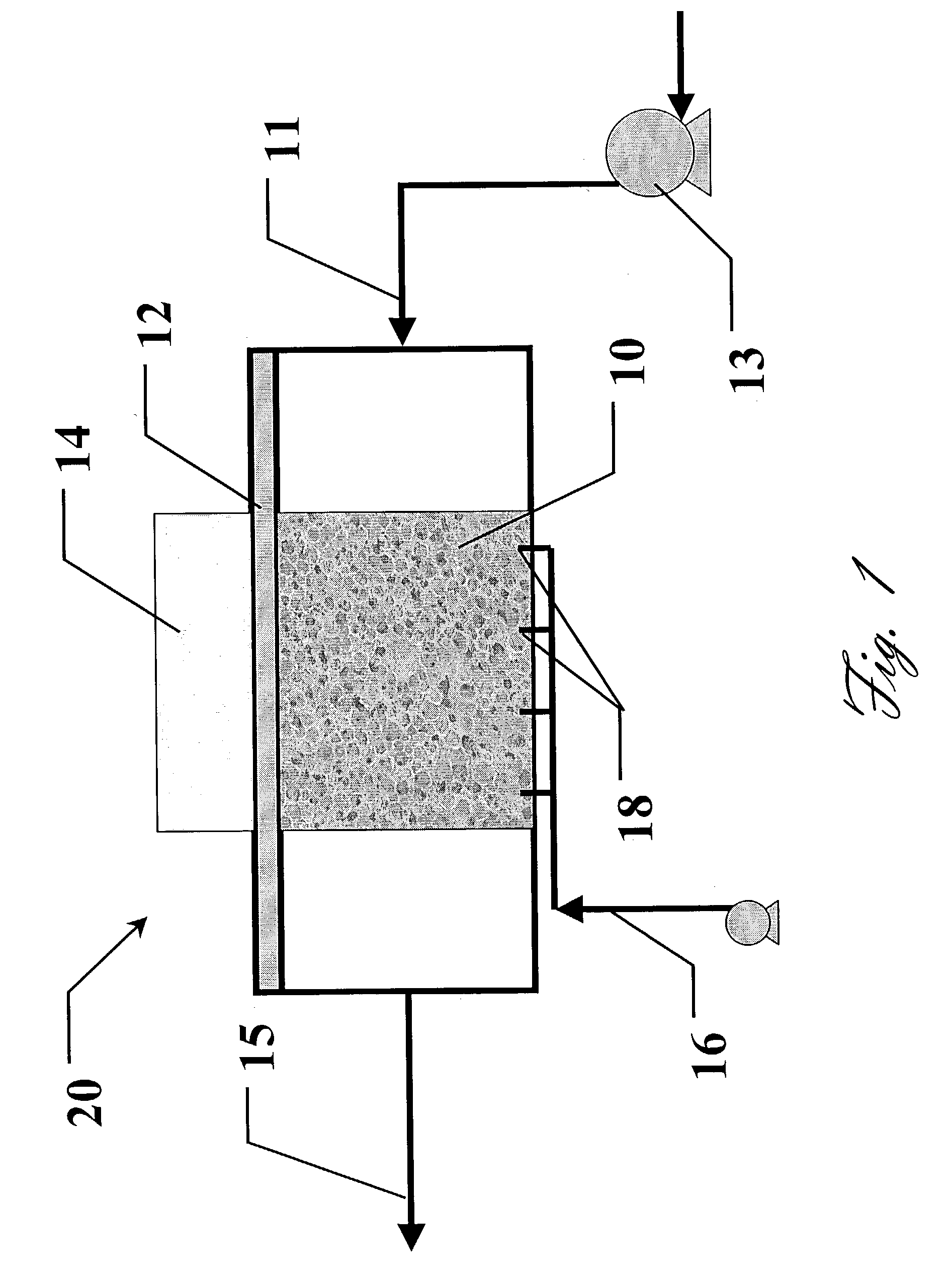
[0018]FIG. 1 illustrates the humidifier 20 in the present invention. For illustrative purposes, the heat from the onboard power electronics 14 is used as the heat source. High conductivity graphite foam 10 is attached to the surface of the spreader plate 12 opposite the power electronics 14 heat source by some means of joining. This foam is ducted in some fashion such that air can be forced through the foam structure. A water supply system 16 is used to add water to the foam at 18. If the foam is properly surface treated (i.e. oxidation at 500° C. for more than 8 hours), the water will wick up through the pores of the foam and be then evaporated as the forced dry air 11 is passed through the foam. A blower / compressor 13 is used to bring in filtered ambient air and force it through the foam. As the air is forced through the foam, the heat from the heat source 14 heats it. Concurrently, the heat from the heat source combined with the now lower humidity level of the incoming air, resul...

second embodiment

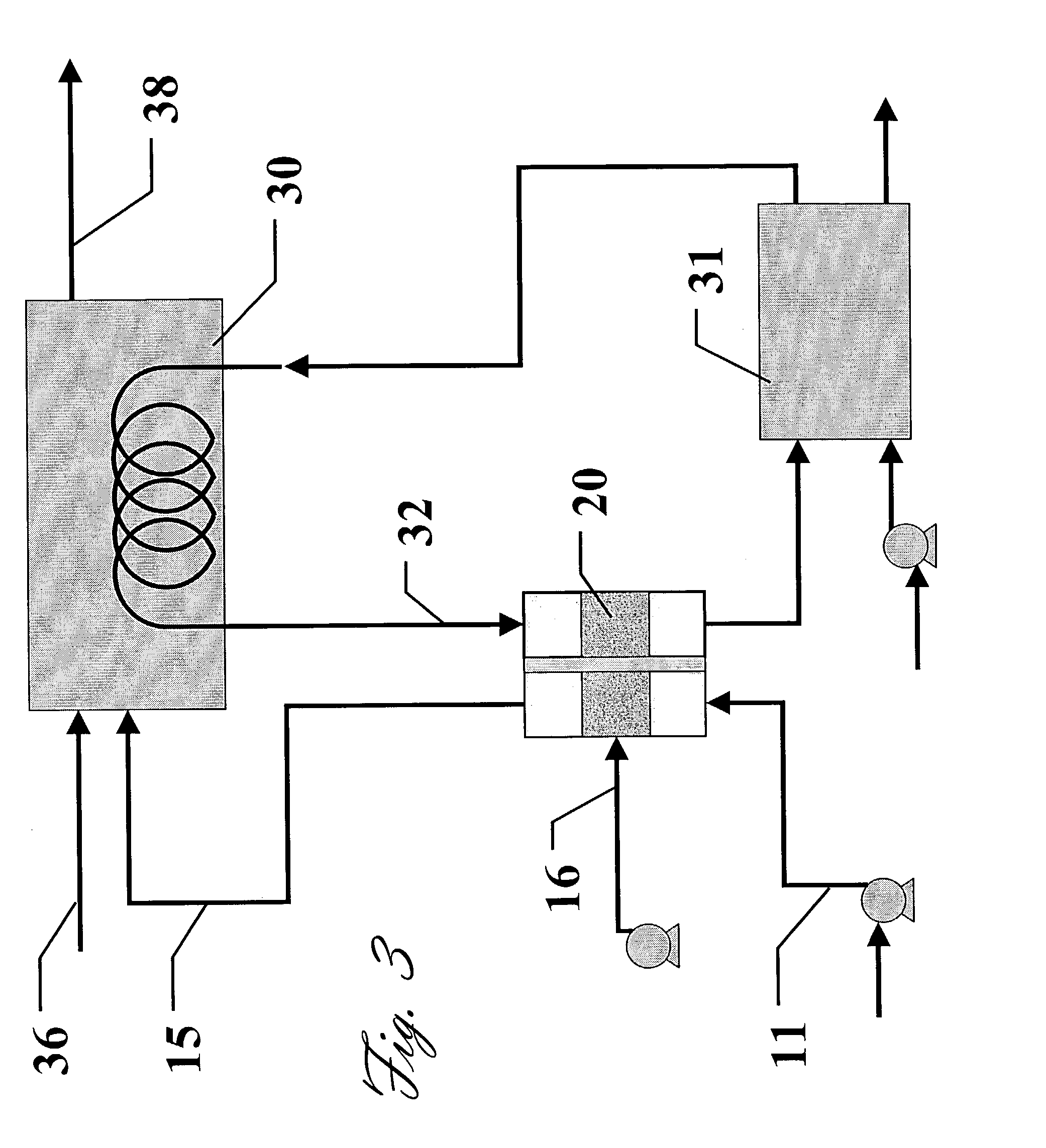
[0023]In another embodiment of the present invention, a similar design is used, but in conjunction with the cooling water of the fuel cell and the radiator (which can be made from high conductivity carbon foam itself). FIG. 3 is a schematic of the This inlet air (considered dry ambient air) 11 is passed through a similar humidifier 20 as in FIG. 1, but with the heat source being the hot cooling fluid 32 exiting the fuel cell 30. The hot cooling fluid 32 supplies enough heat for the humidification process with a similar foam structure on the fluid side (i.e. pin-fin). Depending on the inlet air humidification needs (which is dependent on the ambient humidity), the fuel cell cooling fluid will still need to be cooled further by a radiator 31. The humid fuel cell inlet air 15 is then supplied to the fuel cell 30, as needed, along with optional additional fuel 36 to enable the fuel cell energy production before leaving the fuel cell as exhaust 38. Again, as in FIG. 1, the compressor al...


PUM

PropertyMeasurementUnit
Thermal conductivityaaaaaaaaaa
Electrical conductivityaaaaaaaaaa

Abstract

A method and apparatus of supplying humid air to a fuel cell is disclosed. The extremely high thermal conductivity of some graphite foams lends itself to enhance significantly the ability to humidify supply air for a fuel cell. By utilizing a high conductivity pitch-derived graphite foam, thermal conductivity being as high as 187 W/m·K, the heat from the heat source is more efficiently transferred to the water for evaporation, thus the system does not cool significantly due to the evaporation of the water and, consequently, the air reaches a higher humidity ratio.

Description

CROSS-REFERENCE TO RELATED APPLICATIONS[0001]This application is a continuation-in-part of earlier filed U.S. patent applications Ser. No. 09 / 489,805 filed on Jan. 24, 2000 now abandoned and 09 / 519,559 filed on Mar. 6, 2000 now U.S. Pat, No. 6,673,328, both herein incorporated by reference in their entirety.STATEMENT REGARDING FEDERALLY SPONSORED RESEARCH[0002]The United States Government has rights in this invention pursuant to contract DE-AC05-00OR22725 between the United States Department of Energy and UT-Battelle, LLC.BACKGROUND OF THE INVENTION[0003]The present invention generally relates to pretreatment of fuel cell feed airstreams and specifically to a device and method for humidifying an airstream to a fuel cell using porous carbon foam.[0004]Conventional methods for humidifying air involve spraying water over a high surface area medium (cloth, steel wool, etc) and forcing the dry supply air over the moist medium, which results in evaporation of the water from the surfaces o...

Claims


Application Information

Patent Timeline
IPC IPC(8): B01D1/00C04B38/00F28D5/02F28D20/02F28F13/18F28F21/02
CPCC04B38/00F28D5/02F28D20/023F28F13/18F28F21/02Y02E60/145Y02E60/14
Inventor KLETT, JAMES W.STINTON, DAVID P.
Owner UT BATTELLE LLC
Why Eureka
Try Eureka