
Method of making a golf ball with a multi-layer core

a golf ball and multi-layer technology, applied in the field of multi-layer golf balls, can solve the problems of difficult control around the green, difficult manufacturing of golf balls, and difficulty in feeling

Inactive Publication Date: 2006-12-26
ACUSHNET CO
View PDF124 Cites 106 Cited by
  • Summary
  • Abstract
  • Description
  • Claims
  • Application Information

AI Technical Summary

Benefits of technology

[0042]One advantage of the present invention is that it allows for the manufacture of golf balls having thin layers of material of a relatively uniform thickness. The present invention also allows laminate layers to be more easily formed concentric with the center of the ball. The result is greater flexibility in the design of golf balls in order to obtain excellent playing characteristics, such as resiliency, spin rate, and feel. Moreover, the present invention also simplifies the manufacturing process for making such laminate layers and thereby reduces manufacturing costs.
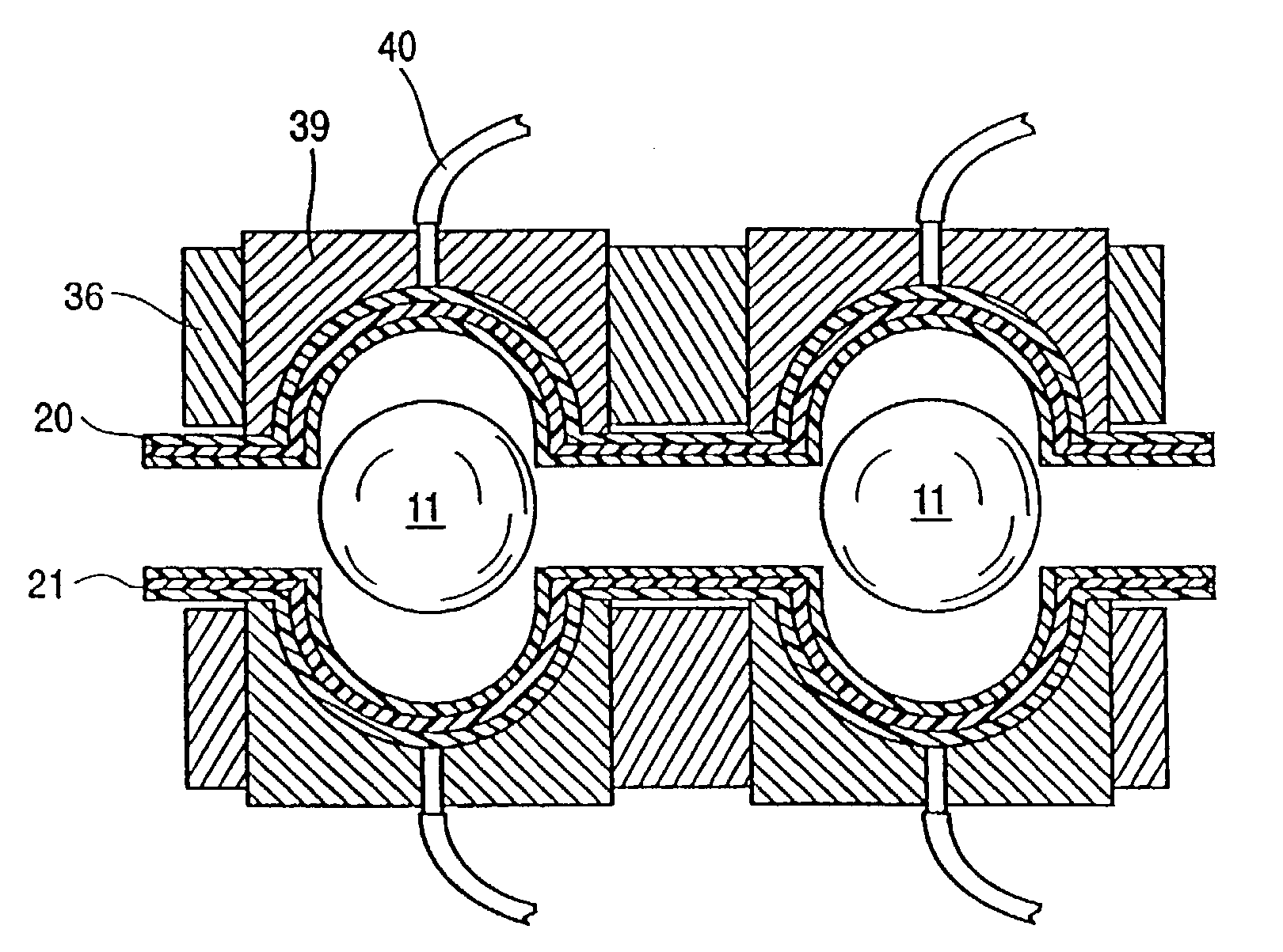
[0043]In particular, the present invention uses raw material in roll stock form to form the shells of the ball by a thermoforming process. Thermoforming processes are high volume methods of producing molded products from a thin sheet of roll stock. While this molding process is principally used with thermoplastic materials, it is also possible to use thermoset materials as well.
[0044]Thermoforming processes generally involve heating a sheet of material until the sheet softens and then forcing the sheet against a cool forming mold by vacuum or pressure. Positive or negative pressure is then employed to push, pull, or stretch the softened sheet into a cavity or onto a protrusion corresponding to the shape of the desired part. The sheet is held in place against the mold surface while it cools. Once it has sufficiently cooled, the sheet retains the shape of the mold even after being removed from the cavity or protrusion. There are several variations of thermoforming, such as vacuum, positive air pressure, plug assist, draping, twin sheet, positive, negative, vacuum snap-back, and billow forming. Some of these techniques are explained in greater detail below to illustrate the invention, although a skilled artisan would understand that a wide variety of additional thermoforming techniques could be used without departing from the spirit and scope of the invention.
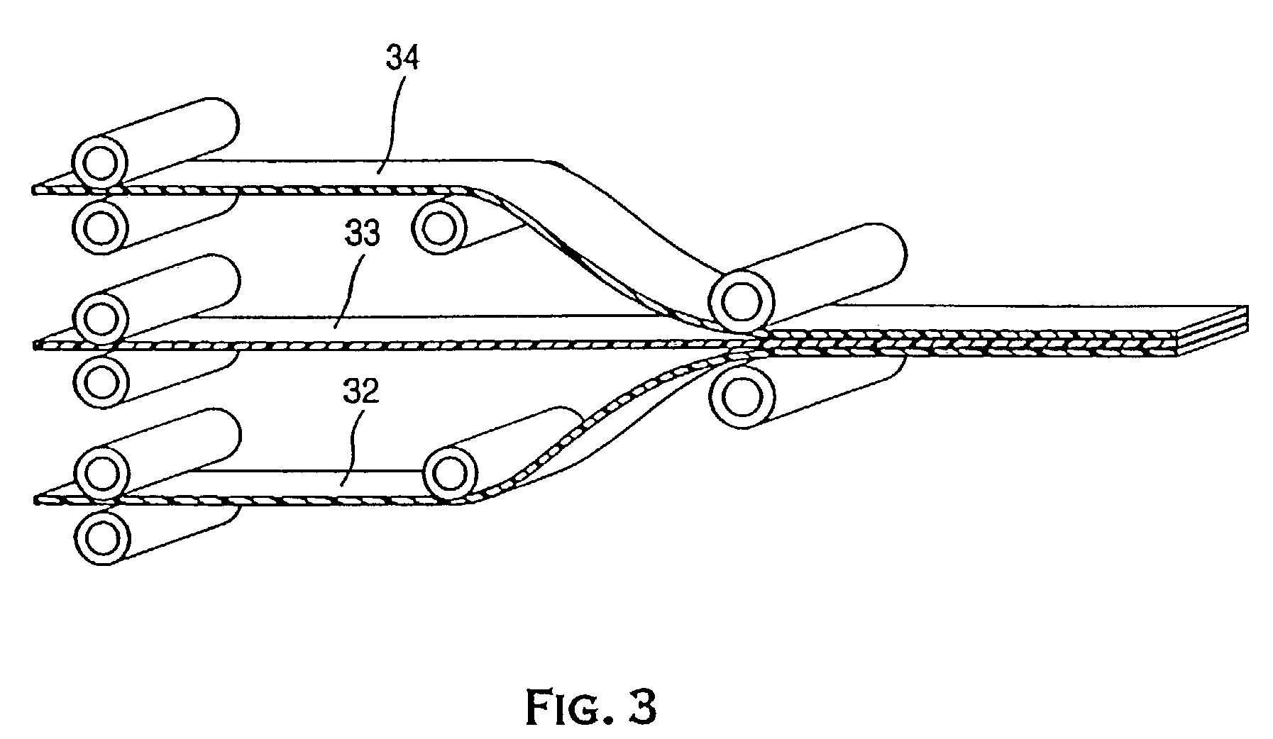
[0045]The sheet of material used in a thermoforming process may be provided in roll stock. Generally, roll stock is a sheet of material that is rolled along its length to form a cylindrical shape. Typically, the roll stock is about 420 mm to about 660 mm wide, and has a thickness corresponding approximately to the desired thickness of the finished product or layer. As explained more fully below, the roll stock is connected to a thermoforming machine and delivered to the forming module.
[0046]FIG. 13 illustrates one embodiment of a thermoforming mold that may be used with the present invention. As shown, the thermoforming machine or process can carry out several stages of the molding process simultaneously. For instance, a portion of the roll stock may be being pre-heated while other portions of the roll stock are being molded, undergoing further processing or finishing, or are being off-loaded for further processing at another location.
[0047]Roll stock is connected to the thermoforming machine at a loading station. In this embodiment, roll stock is rolled or wrapped around a cylindrical tube that may be placed on a roller so that it can rotate as layer material is supplied to the forming module. As the material is unwound, it is preheated and then molded into its desired shape.

Problems solved by technology

However, wound balls are generally difficult to manufacture when compared to solid golf balls.
Golf balls having a hard core and a hard cover generally have very high resiliency for distance, but are hard feeling and difficult to control around the greens.
Moreover, while the benefits of laminate layers may be generally recognized, manufacturing laminate layers on a golf ball presents several challenges that have largely precluded their use.
For example, as the desired thickness of the laminate layers becomes thinner, it is increasingly more difficult to maintain a relatively uniform layer thickness and concentric orientation around the ball using conventional manufacturing methods known in the golf industry.
The forces applied to the core to hold it in place may cause the core surface to deform slightly.
Compression molding, which physically compresses both the layer material and the core in order to form the layer, presents similar manufacturing difficulties as the desired layer thickness becomes thin.
Moreover, the use of casting only allows for one layer to be formed on the golf ball at a time.
Thus, the manufacture of a golf ball having a plurality of laminate layers would require even more time.

Method used


Image

  • Method of making a golf ball with a multi-layer core
  • Method of making a golf ball with a multi-layer core
  • Method of making a golf ball with a multi-layer core

Examples


example 1

[0200]Table 1 sets forth an example of the core contents, i.e., center and inner layers, according to one embodiment of the invention. The fillers used in the compositions of these examples are regrind and barium sulfate (BaSO4). Vulcup 40KE® and Varox 231XL® are free radical initiators, and are a-a bis (t-butylperoxy) diisopropylbenzene and 1,1-di (t-butylperoxy) 3,3,5-trimethyl cyclohexane, respectively.

[0201]

TABLE 1Core Compositions (pph, based on 100 parts of polybutadiene)Layer No.Center123Polybutadiene100100100100Polywate 32526231813Vulcup 40KE ®0.30.30.30.3Varox 231XL ®0.60.50.50.5BaSO431262525Zinc Diacrylate30323547SR-3502226Calcium Oxide3000Zinc Oxide0366

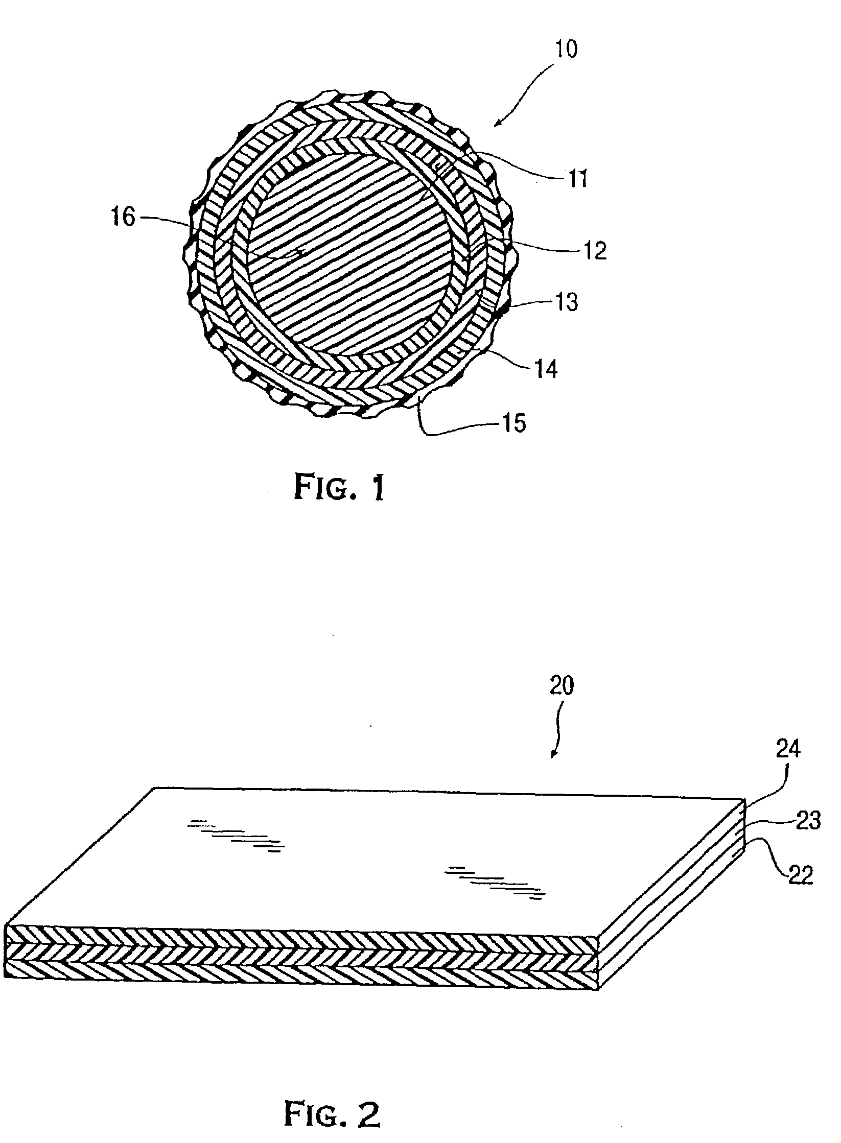
[0202]The center 11 set forth in Table 1, has a Shore C hardness of about 65 at the center point thereof and a Shore C hardness of about 68 at the midpoint between the center and the outer edge. The first layer 12 is harder than the center 11 and has a Shore C hardness of about 71. The second layer 13 is harder than the fir...

example 2

[0208]The center of the second embodiment, as set forth in Table 3, has a Shore C hardness of about 77. The first layer is softer than the center and has a Shore C hardness of about 73. The second layer is softer than the first layer and has a Shore C hardness of about 71. The third layer is softer than the second layer and has a Shore C hardness of about 68. The cover of the second embodiment golf ball is a harder cover than that used with the first embodiment and includes a blend of about 50 / 50 by weight of a standard sodium ionomer and a standard lithium ionomer. The cover, as described in Table 4, has a Shore D hardness of about 65 to 70.

[0209]Table 3 sets forth the contents of the golf ball core in the second embodiment. The compositions used to prepare the golf ball core of this embodiment are all in parts per hundred (pph), based on 100 parts of polybutadiene.

[0210]In the second embodiment, the center 11 of the core 16 was compression molded to a diameter of about 1.39 inches...

example 3

[0213]Table 4 below provides batch compositions for intermediate layer blends for forming the novel multilayer golf balls of the present invention. However, it is to be understood that the examples are only for illustrative purposes and in no manner is the present invention limited to the specific disclosures therein.

[0214]In particular, batch numbers 2-4 provide intermediate layer blends including NUCREL® 960, HYTREL® 3078, and ZnO used to form the intermediate layers of the golf balls of the present invention. Batch number 1 provides a control intermediate layer blend.

[0215]

TABLE 4Intermediate Layer FormulationsFlexuralBatch% NUCREL ®% HYTREL ®%ModulusSpecific#9603078ZnO(psi)Gravity1—802042101.27210751555601.21320701077101.1743065 572501.14


PUM

PropertyMeasurementUnit
Lengthaaaaaaaaaa
Lengthaaaaaaaaaa
Thicknessaaaaaaaaaa

Abstract

A method for making a multilayer golf ball including a solid center having a center hardness, a plurality of laminates cut into a plurality of shapes formed around the center to create an inner ball, and a cover formed around the inner ball, wherein the plurality of layers can include at least a first layer having a hardness greater than the center hardness and a second layer having a hardness greater than the first layer hardness, and optionally a third layer disposed between the first and the second layers having a hardness greater than the first layer hardness.

Description

CROSS REFERENCE TO RELATED APPLICATIONS[0001]This application is a continuation-in-part of the U.S. patent application Ser. No. 09 / 948,692, filed Sep. 10, 2001 now U.S. Pat. No. 7,014,573, which is a continuation-in-part of U.S. patent application Ser. No. 09 / 172,608, filed Oct. 15, 1998, now U.S. Pat. No. 6,302,808, which is a divisional of U.S. patent application Ser. No. 08 / 943,932, filed Oct. 3, 1997, now U.S. Pat. No. 6,056,842, and also a continuation-in-part of U.S. patent application Ser. No. 09 / 630,387, filed Aug. 1, 2000 now U.S. Pat. No. 6,458,892, which is a continuation-in-part of U.S. patent application Ser. No. 08 / 603,057, filed Feb. 16, 1996, now U.S. Pat. No. 5,759,676, and a continuation-in-part of U.S. patent application Ser. No. 08 / 996,718, filed Dec. 23, 1997, now U.S. Pat. No. 6,124,389, which is a continuation-in-part of U.S. patent application Ser. No. 08 / 746,362, filed Nov. 8, 1996, now U.S. Pat. No. 5,810,678, which is a continuation-in-part of U.S. patent ...

Claims


Application Information

Patent Timeline
IPC IPC(8): B29C51/14A63B37/00A63B45/00B29C43/14B29C43/18B29C43/30B29C70/70B29D99/00B32B7/022C08F210/02C08L9/00C08L21/00C08L23/08C08L51/00C08L53/00C08L53/02
CPCA63B37/0003A63B37/0037A63B37/0049A63B37/0075A63B37/0076A63B45/00B29C43/027B29C43/146B29C43/18B29C51/02B29C51/14B29C51/16B29C63/22B29C70/70B29D99/0042B32B1/00B32B7/02B32B25/04B32B25/16B32B27/327B32B27/40C08L9/00C08L23/08C08L23/0869C08L23/0876C08L51/00C08L51/006C08L53/00C08L53/02C08L75/04A63B37/0087A63B37/0031A63B37/0033A63B37/0043A63B37/0045A63B37/0047A63B37/0061A63B37/0062A63B37/0064A63B37/0065A63B37/0066A63B2037/0079B29C33/0022B29C43/305B29C43/46B29C45/1671B29C2043/023B29C2043/3644B29C2791/001B29K2101/10B29K2101/12B29K2105/256B29L2009/00B29L2031/52B29L2031/54B29L2031/545B32B2274/00B32B2307/536B32B2307/546C08F210/02C08L21/00C08L2205/02C08L2205/03C08L2666/08C08L2666/14C08L2666/24C08L2666/04C08L2666/02C08L2666/06C08L2666/20C08F220/06C08F220/12A63B37/0039B32B7/022A63B37/00621
Inventor BRUM, WILLIAMDALTON, JEFFREY L.BOEHM, HERBERT C.CAVALLARO, CHRISTOPHER
Owner ACUSHNET CO
Learn More