Inductively-coupled torodial plasma source

a plasma source and inductively coupled technology, applied in plasma welding apparatus, plasma technique, plasma manufacturing tools, etc., can solve the problems of high voltage on the drive coil, inefficient rf inductively coupled plasma, and high cost of power delivery system, so as to facilitate the operation of the plasma source and reduce the potential difference. , the effect of high loop voltag

Inactive Publication Date: 2007-01-23
MKS INSTR INC
View PDF188 Cites 57 Cited by
  • Summary
  • Abstract
  • Description
  • Claims
  • Application Information

AI Technical Summary

Benefits of technology

[0013]In one embodiment, the plasma chamber is formed of metal. Metal plasma chambers include multiple dielectric regions that prevent induced current flow from forming in the plasma chamber. In one embodiment, the metal plasma chamber is segmented with multiple dielectric gaps to reduce the potential difference between the plasma and the metal plasma chamber, thereby distributing the plasma loop voltage across multiple dielectric gaps. The segmented plasma chamber facilitates operating the plasma source at relatively high loop voltages, while reducing or eliminating the plasma channel surface erosion. In another embodiment, circuit elements are used to control the voltage distribution across the metal plasma chamber.
[0014]In one embodiment, the power supply of the high power source includes a voltage regulator circuit that provides a stable DC bus voltage that allows the user to precisely control the total power supplied to the plasma. In one embodiment, the high power toroidal plasma source of the present invention includes an apparatus for reliably igniting the plasma.
[0015]The high power toroidal plasma source of the present invention has numerous advantages. The high power plasma source generates a relatively high power plasma with higher operating voltages that has increased dissociation rates and that allow a wider operating pressure range. Also, the high power plasma source has precise process control. In addition, the high power plasma source has relatively low plasma chamber surface erosion.
[0017]In another embodiment, the plasma chamber is formed of an electrically conductive material and at least one dielectric region that forms an electrical discontinuity in the conductive material. The electrically conductive material may be aluminum and the aluminum may be anodized. The electrically conductive material may be segmented with at least two dielectric gaps. The dielectric gaps reduce the potential difference between the plasma and the metal plasma chamber, thereby distributing the plasma loop voltage across the at least two dielectric gaps. A voltage divider circuit may be electrically coupled across the at least two dielectric gaps to distribute the plasma loop voltage across the at least two dielectric gaps.
[0022]The apparatus includes an apparatus to assist in igniting the plasma. In one embodiment, an electrode is positioned in the plasma chamber that generates free charges that assist the ignition of the plasma in the plasma chamber. In another embodiment, the apparatus includes a secondary winding that resonates with the primary winding and raises the voltage in the plasma chamber to assist ignition of the plasma in the plasma chamber. In another embodiment, an ultraviolet light source is optically coupled to the plasma chamber. The ultraviolet light source generates free changes that assist the ignition of the plasma in the plasma chamber.

Problems solved by technology

For example, some applications require the use of ions with low kinetic energy (i.e. a few electron volts) because the material being processed is sensitive to damage.
However, microwave and inductively coupled plasma sources require expensive and complex power delivery systems.
However, prior art RF inductively coupled plasmas are not purely inductive because the drive currents are only weakly coupled to the plasma.
Consequently, RF inductively coupled plasmas are inefficient and require the use of high voltages on the drive coils.
The ion bombardment deteriorates the reactor and can contaminate the process chamber and the material being processed.
The ion bombardment can also cause damage to the material being processed.
However, because of the relatively weak coupling of the drive coil currents to the plasma, large eddy currents form in the shields resulting in substantial power dissipation.
The cost, complexity, and reduced power efficiency make the use of Faraday shields unattractive.

Method used


Image

  • Inductively-coupled torodial plasma source
  • Inductively-coupled torodial plasma source
  • Inductively-coupled torodial plasma source

Examples


Embodiment Construction

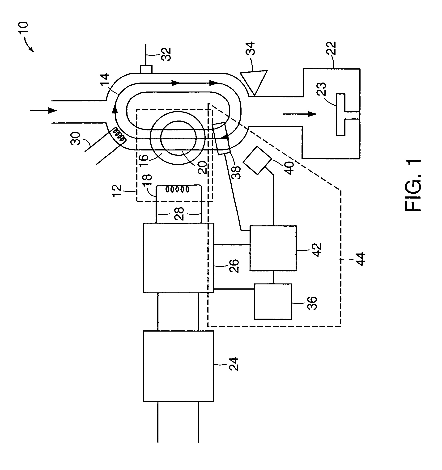
[0039]FIG. 1 is a schematic representation of a toroidal low-field plasma source 10 for producing activated gases that embodies the invention. The source 10 includes a power transformer 12 that couples electromagnetic energy into a plasma 14. The power transformer 12 includes a high permeability magnetic core 16, a primary coil 18, and a plasma chamber 20 that contains the plasma 14, which allows the plasma 14 to form a secondary circuit of the transformer 12. The power transformer 12 can include additional magnetic cores and primary coils (not shown) that form additional secondary circuits.

[0040]One or more sides of the plasma chamber 20 are exposed to a process chamber 22 to allow charged particles and activated gases generated by the plasma 14 to be in direct contact with a material to be processed (not shown). A sample holder 23 may be positioned in the process chamber 22 to support the material to be processed. The material to be processed may be biased relative to the potentia...


PUM

PropertyMeasurementUnit
pressureaaaaaaaaaa
diameteraaaaaaaaaa
electric fieldsaaaaaaaaaa

Abstract

Apparatus for dissociating gases includes a plasma chamber comprising a gas. A first transformer having a first magnetic core surrounds a first portion of the plasma chamber and has a first primary winding. A second transformer having a second magnetic core surrounds a second portion of the plasma chamber and has a second primary winding. A first solid state AC switching power supply including one or more switching semiconductor devices is coupled to a first voltage supply and has a first output that is coupled to the first primary winding. A second solid state AC switching power supply including one or more switching semiconductor devices is coupled to a second voltage supply and has a second output that is coupled to the second primary winding. The first solid state AC switching power supply drives a first AC current in the first primary winding. The second solid state AC switching power supply drives a second AC current in the second primary winding. The first AC current and the second AC current induce a combined AC potential inside the plasma chamber that directly forms a toroidal plasma that completes a secondary circuit of the transformer and that dissociates the gas.

Description

RELATED APPLICATIONS[0001]This is a continuation of patent application Ser. No. 09 / 804,650, filed on Mar. 12, 2001 now U.S. Pat. No. 6,815,633, which is a continuation-in-part of patent application Ser. No. 09 / 774,165, filed on Jan. 26, 2001 now U.S. Pat. No. 6,924,455, which is a continuation-in-part of patent application Ser. No. 09 / 659,881, filed on Sep. 12, 2000, now U.S. Pat. No. 6,486,431, which is a continuation of patent application Ser. No. 08 / 883,281, filed on Jun. 26, 1997, now U.S. Pat. No. 6,150,628, the entire disclosures of which are incorporated herein by reference.FIELD OF THE INVENTION[0002]This invention relates generally to the field of generating activated gas containing ions, free radicals, atoms and molecules and to apparatus for and methods of processing materials with activated gas.BACKGROUND OF THE INVENTION[0003]Plasma discharges can be used to excite gases to produce activated gases containing ions, free radicals, atoms and molecules. Activated gases are ...

Claims


Application Information

Patent Timeline
Patent Type & Authority Patents(United States)
IPC IPC(8): B23K10/00
CPCH05H1/46H05H1/24H05H1/4652H05H2242/22
Inventor CHEN, XINGHOLBER, WILLIAM M.COWE, ANDREW BARNETTGEORGELIS, ERICBYSTYAK, ILYA M.BORTKIEWICZ, ANDRZEJ
Owner MKS INSTR INC
Why Eureka
Try Eureka