Method for driving an ultrasonic system to improve acquisition of blade resonance frequency at startup

a technology of ultrasonic system and blade, which is applied in the field of ultrasonic devices, can solve the problems of relatively wide thermal tissue damage, uncontrolled or undamped vibration and heat, vaporization and fumes, etc., and achieves improved and more pronounced resonance, improved ultrasonic ability, and high drive current

Inactive Publication Date: 2007-02-20
ETHICON ENDO SURGERY INC
View PDF14 Cites 615 Cited by
  • Summary
  • Abstract
  • Description
  • Claims
  • Application Information

AI Technical Summary

Benefits of technology

[0020]The invention is a method for improving the ability of an ultrasonic system to sweep and lock onto a resonance frequency of a blade subjected to a heavy load at startup. This is accomplished by applying a high drive voltage or a high drive current. Increasing the drive signal to the hand piece results in an improved and more pronounced resonance as viewed when using a spectrum analyzer. That is, under load, the increased drive signal causes the maximum phase to become higher (more inductive), and the minimum impedance magnitude and the maximum impedance magnitude to respectively become lower and higher. Thus, increasing the excitation drive signal to the hand piece / blade at startup significantly alleviates the limiting factors associated with ultrasonic generators, which results in an increase of the maximum load capability at startup.
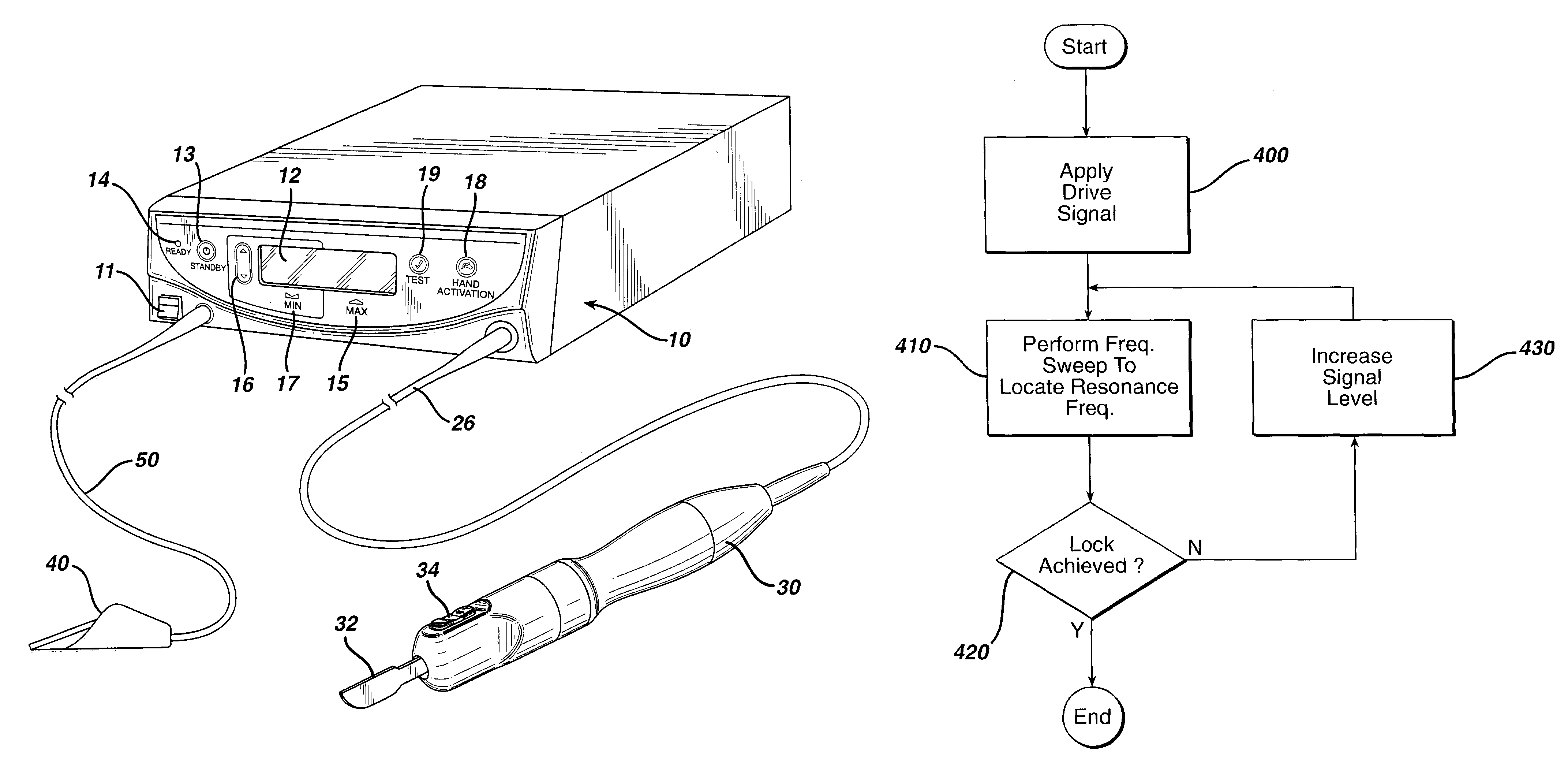
[0021]In accordance with the invention, the blade is driven with a progressively stronger signal, which permits a faster and more accurate identification of the actual operational resonance of the blade, and avoids inadvertently considering other resonance as the desired resonance frequency. Undesired resonance modes, such as transverse modes of resonance (i.e., a vibration along an axis which is perpendicular to the longitudinal axis of vibration of the hand piece / blade), are not excited until the energy levels which vibrate the blade are at a substantial level. This effect is advantageously utilized to initially ultrasonically drive the blade at very low levels across its known frequency range of resonance. The intended operational resonance of the blade is recognized by performing resonance impedance measurements during the sweep, and this impedance at resonance is more robust and discernable than other undesired resonances which require more energy to resonate efficiently. If no resonance is located, the drive intensity is increased and another sweep is performed. This method is repeated at sequentially higher drive levels until the blade resonance is acquired.
[0022]In an embodiment of the invention, a moderate to intense drive signal is applied to the blade during the sweep to locate the resonance frequency (rather than starting the sweep with a low level drive signal). If multiple resonances are encountered, the sweep is repeated at progressively lower levels until only one primary resonance is observed. Further, a method of using this embodiment of the present invention improves startup performance of the ultrasonic system while minimizing transducer ringing, which is especially noticeable under a “no-load” situation, when the system Q (i.e., the minimum system impedance) is high and the phase response slope in the phase-frequency plot is large. An additional benefit of starting the sweep at a high drive level is the ability to obtain a more robust resonance frequency of a heavily dampened blade which permits faster resonance frequency identification and lock.
[0023]In another embodiment of the invention, a progressively wider sweep is performed, and a drive signal whose intensity is changed based on observed resonances. Such a combination provides the benefits of both a narrow sweep, which saves time, and high power, which assures it is possible to resonate a blade. For example, a narrow sweep at a high drive level is initially performed. If a resonance is not found, then the sweep is widened. If multiple resonances are found, the signal level is then reduced. Sweeping in this manner facilitates rapid identification of the desired resonance frequency of a dampened blade without inadvertently driving the blade at an undesired resonance frequency.
[0024]In an additional embodiment of the invention, the sweep for resonance is started from the most center or ideal resonance frequency for a blade. If no resonance is located, a check of frequencies at an increasing distance from the center or ideal frequency of the blade is performed, such as a very tight sweep which concentrates on a frequency range in the immediate vicinity of the ideal resonance frequency. If no resonance is found, then a check of the frequencies located slightly outward from the initial frequency range is performed. If no resonance is found here, then the swept frequency range is expanded and the search for the resonance frequency is again performed. To save time, each progressively wider frequency sweep skips frequencies previously covered, concentrating only on the unchecked frequencies within the revised wider range. Thus, identification of the resonance frequency is accelerated since most blades possess a primary resonance frequency which is closer statistically to the center or ideal frequency.
[0025]The method of the invention provides an ultrasonic system with the ability to start under a larger load. The method also provides the system with the ability to start faster and to lock onto the resonance frequency of the blade more readily, reduces problems related to “gunk” or debris lodged between the blade and sheath, and improves the loading capacity of the blade tip once it is applied to tissue. That is, the system will remain locked onto the resonance frequency of the blade during use under larger loads. In addition, a user will experience less difficulties during the operation of the ultrasonic surgical blade system because tissue loading capabilities and immunity to loss of lock due to “gunk” are significantly improved. Simplification of blade design is also achieved because secondary resonances can be placed at locations which are closer to the center or ideal resonance frequency of the blade without the traditional danger of the generator locking onto the secondary resonances. The design of the blade is further simplified because the primary resonance frequency of the blade can be placed further from the center frequency, yet still be identified through progressively wider searches for the resonance frequency.

Problems solved by technology

However, such instruments employ very high temperatures to achieve coagulation, causing vaporization and fumes as well as splattering.
Additionally, the use of such instruments often results in relatively wide zones of thermal tissue damage.
One of the problems associated with such ultrasonic cutting instruments is uncontrolled or undamped vibrations and the heat, as well as material fatigue resulting therefrom.
However, this could result in insufficient power to the blade at a time when it is needed for the most effective treatment of the patient.
In response to a switch on the hand piece or a foot switch connected to the generator by another cable, the generator signal is applied to the transducer, which causes a longitudinal vibration of its elements.
This arrangement is inflexible since the power versus load characteristics of the output of such a system can not be optimized to various types of hand piece transducers and ultrasonic blades.
The performance of traditional analog ultrasonic power systems for surgical instruments is affected by the component tolerances and their variability in the generator electronics due to changes in operating temperature.
However, these traditional ultrasonic drive systems have little or no flexibility with regards to adaptive frequency control.
The prior art ultrasonic generator systems also have little flexibility with regard to amplitude control, which would allow the system to employ adaptive control algorithms and decision making.
For example, these fixed systems lack the ability to make heuristic decisions with regards to the output drive, e.g., current or frequency, based on the load on the blade and / or the current to voltage phase angle.
It also limits the system's ability to set optimal transducer drive signal levels for consistent efficient performance, which would increase the useful life of the transducer and ensure safe operating conditions for the blade.
Further, the lack of control over amplitude and frequency control reduces the system's ability to perform diagnostic tests on the transducer / blade system and to support troubleshooting in general.
There are problems associated with existing ultrasonic systems.
For example, such systems experience difficulty starting while the blade is under certain load conditions.
A major complaint of users of such ultrasonic generators is their failure to start under a moderate to heavy load.
In the presence of a light to moderate load, debris between the blade and the blade sheath can load the blade such that startup or the ability of the blade to start in free standing air is degraded.
However, it is not possible to achieve startup using such a hand piece / blade when it is subjected to a heavy load at a low voltage.
This can result in either of the following conditions: First, a limitation experienced with startup under load results from an insufficient current feedback signal level.
Second, another limiting factor is “sticktion,” i.e., the blade getting stuck in the load.
Here, the energy applied to the hand piece is insufficient to initiate blade motion, and the hand piece / blade responds as if there is a very large mechanical load.
This condition may result in a highly damped hand piece / blade where the phase angle between the current and voltage never crosses zero, resulting an inability to detect resonance using zero crossing.
A further limiting effect is gunking of the blade, i.e., the embedding of blood and other debris between the blade and the sheath to thereby load down the blade.
This “wide sweep” approach has several problems.
First, locating the resonance is time consuming.
If the sweep begins at one end of the sweep range, but the primary resonance is at the other end, a considerable amount of time is consumed to find the primary resonance.
Second, it is possible to mistake a secondary resonance (a resonance not desired) for the primary resonance.
However, limiting the sweep range complicates blade design since the permitted primary resonance range of a blade becomes limited, and thus adds constraints to blade designs.
Another problem present in conventional ultrasonic devices is that the stability of the frequency control lock for power is affected by “ringing” of the transducer as the frequency approaches the resonance area of the blade.

Method used


Image

  • Method for driving an ultrasonic system to improve acquisition of blade resonance frequency at startup
  • Method for driving an ultrasonic system to improve acquisition of blade resonance frequency at startup
  • Method for driving an ultrasonic system to improve acquisition of blade resonance frequency at startup

Examples


Embodiment Construction

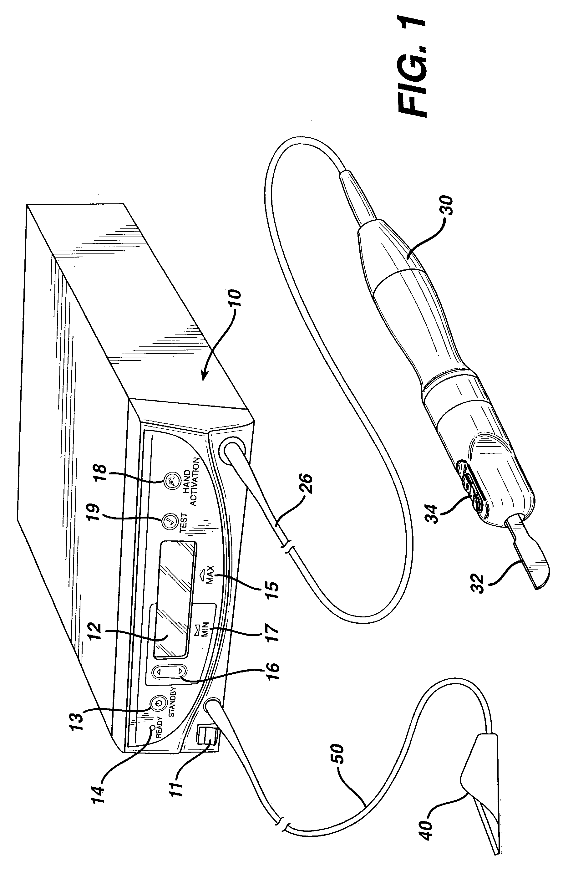
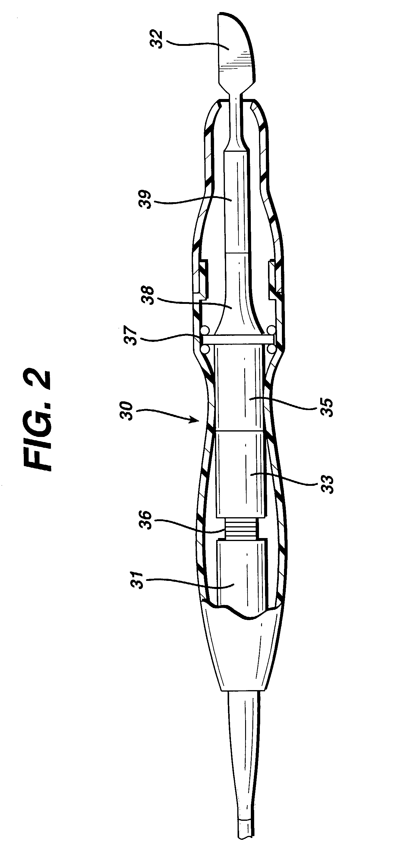
[0035]FIG. 1 is an illustration of a system for implementing the method in accordance with the invention. By means of a first set of wires in cable 26, electrical energy, i.e., drive current, is sent from the console 10 to a hand piece 30 where it imparts ultrasonic longitudinal movement to a surgical device, such as a sharp scalpel blade 32. This blade can be used for simultaneous dissection and cauterization of tissue. The supply of ultrasonic current to the hand piece 30 may be under the control of a switch 34 located on the hand piece, which is connected to the generator in console 10 via wires in cable 26. The generator may also be controlled by a foot switch 40, which is connected to the console 10 by another cable 50. Thus, in use a surgeon may apply an ultrasonic electrical signal to the hand piece, causing the blade to vibrate longitudinally at an ultrasonic frequency, by operating the switch 34 on the hand piece with his finger, or by operating the foot switch 40 with his ...


PUM


Abstract

The ability of an ultrasonic system to sweep and lock onto a resonance frequency of a blade subjected to a heavy load at startup is improved by applying a high drive voltage or a high drive current while systematically increasing the level of the applied signal. Increasing the drive signal to the hand piece results in an improved and more pronounced “impedance spectrum.” That is, under load, the increased drive signal causes the maximum phase margin to become higher and the minimum/maximum impedance magnitude to become more pronounced. Increasing the excitation drive signal to the hand piece/blade at startup significantly alleviates the limiting factors associated with ultrasonic generators, which results in an increase of the maximum load capability at startup.

Description

RELATED APPLICATIONS[0001]The present invention relates to, and claims priority of, U.S. Provisional Patent Application Ser. No. 60 / 241,895 filed Oct. 20, 2000, and U.S. application Ser. No. 09 / 866,948, having the same title as the present invention, which are incorporated herein by reference.BACKGROUND OF THE INVENTION[0002]1. Field of the Invention[0003]The present invention generally relates to the field of ultrasonic devices and, more particularly, to a method for improving the ability of an ultrasonic system to sweep and lock onto a resonance frequency of a blade subjected to a heavy load at startup.[0004]2. Description of the Related Art[0005]It is known that electric scalpels and lasers can be used as a surgical instrument to perform the dual function of simultaneously effecting the incision and hemostatis of soft tissue by cauterizing tissues and blood vessels. However, such instruments employ very high temperatures to achieve coagulation, causing vaporization and fumes as w...

Claims


Application Information

Patent Timeline
Patent Type & Authority Patents(United States)
IPC IPC(8): A61B17/32A61B17/00
CPCA61B17/320068A61B2017/00725A61B2017/00026A61B2017/320069A61B2017/320071A61B2017/320089
Inventor FRIEDMAN, ALLAN L.DONOFRIO, WILLIAM T.WIENER, EITAN T.BROTZ, JOSEPH A.HEIN, JOHN E.
Owner ETHICON ENDO SURGERY INC
Why Eureka
Try Eureka