Integrated type optical head with sheet waveguide and light coupler

a technology of integrated optical heads and waveguides, applied in the field of optical heads, can solve the problems of deteriorating detection sensibility of optical detectors with respect to variations in wavelengths of light reflected by optical discs, and achieve the effect of improving input coupling efficiency

Inactive Publication Date: 2007-02-27
SAMSUNG ELECTRONICS CO LTD
View PDF29 Cites 29 Cited by
  • Summary
  • Abstract
  • Description
  • Claims
  • Application Information

AI Technical Summary

Benefits of technology

[0011]To solve the above and other problems, it is an aspect of the present invention to provide a compact, integrated optical head for providing an optical intensity required for recording and reproduction by improving an input coupling efficiency between a light source and a light guiding layer and an output coupling efficiency between the light guiding layer and an optical disc.

Problems solved by technology

In addition, the detection sensibility of an optical detector with respect to a variation in the wavelength of light reflected by the optical disc is deteriorated.

Method used


Image

  • Integrated type optical head with sheet waveguide and light coupler
  • Integrated type optical head with sheet waveguide and light coupler
  • Integrated type optical head with sheet waveguide and light coupler

Examples


first embodiment

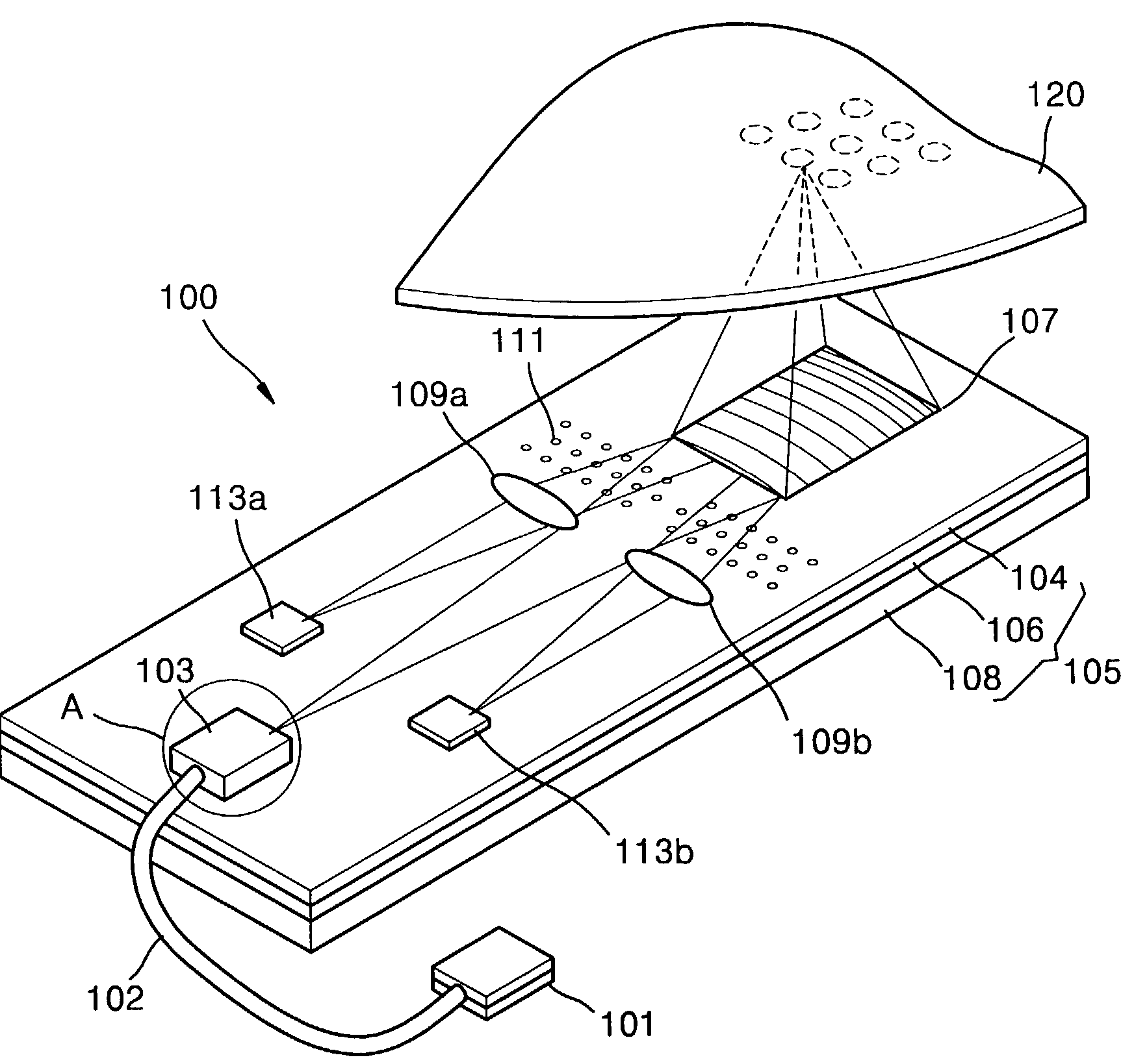
[0061]FIG. 4 is a perspective view of an optical head adopting an evanescent coupler, according to the present invention. Referring to FIG. 4, a laser diode 101 is used as a light source. An evanescent coupler 103 couples an optical fiber 102 to a waveguide 105. The waveguide 105 guides light passed through the evanescent coupler 103. A focusing grating coupler 107 diffracts light from the waveguide 105 onto an optical disc 120. A photonic crystal mirror 111 serves as a light path changing unit for changing the path of light that has been reflected by the optical disc 120 and passed through the focusing grating coupler 107. Mode index lenses 109a and 109b focus the light passed through the photonic crystal mirror 111 on optical detectors 113a and 113b. The optical detectors 113a and 113b convert the received light into an electrical signal. The waveguide 105 is formed by stacking a buffer layer 106 and a light guiding layer 104 on a substrate 108.

[0062]Instead of the laser diode 101...

second embodiment

[0079]FIG. 6 is a cross-section of an optical head adopting a prism coupler, according to the present invention. The prism coupler also adopts the above-described evanescent field coupling technique.

[0080]As shown in FIG. 6, an optical head 130 according to the second embodiment of the present invention employs a prism coupler 133 instead of the evanescent coupler 103 in the optical head according to the first embodiment of the present invention. The prism coupler 133 is installed between the laser diode 101 and the waveguide 105. A collimating lens 132 is further provided between the laser diode 101 and the prism coupler 133. The other elements are installed likewise the optical head according to the first embodiment of the present invention.

[0081]Light emitted from the laser diode 101 is collimated by the collimating lens 132 and heads toward the prism coupler 133. The light incident upon the prism coupler 133 travels through the waveguide 105 and enters the focusing grating coupl...

fourth embodiment

[0091]FIG. 8 is a cross-section of an optical head 150 adopting a tapered coupler, according to the present invention. The optical head 150 includes a tapered coupler 153 manufactured by tapering one end of the light guiding layer 104.

[0092]Referring to FIG. 8, the optical head 150 includes the light source 101, the optical fiber 102, the waveguide 105, the focusing grating coupler 107, the photonic crystal mirror 111, the mode index lens 109, and the optical detector 113. The optical fiber 102 is coupled to the light source 101 so that light travels. The waveguide 105 has a rear end into which the optical fiber 102 is inserted. The tapered coupler 153 is formed on the waveguide 105. The focusing grating coupler 107 diffracts light that travels through the waveguide 105, and focuses the light on the optical disc 120. The photonic crystal mirror 111 changes the light path of light reflected by the optical disc 120. The mode index lens 109 focuses light passed through the photonic cry...


PUM

PropertyMeasurementUnit
optical pathaaaaaaaaaa
optical axisaaaaaaaaaa
optical intensityaaaaaaaaaa

Abstract

An integrated optical head is provided. In the integrated optical head, a light source emits light. A waveguide guides the light. An input coupler is located at one edge of the waveguide, and couples light emitted from the light source and transmits the coupled light to the waveguide. An output coupler is located at another edge of the waveguide, and couples light emitted from the waveguide and focuses the coupled light on an optical disc. A light path changing unit is installed on the waveguide, and changes the light path of light that has been reflected by the optical disc and then passed through the output coupler. An optical detector receives the light passed through the light path changing unit and converts the received light into an electrical signal in order to detect information from the optical disc Accordingly, an input coupling efficiency and an output coupling efficiency are improved, such that light loss is reduced. Thus, recording and reproduction of an optical head can be improved, and a light, compact, integrated optical head can be obtained.

Description

BACKGROUND OF THE INVENTION[0001]This application claims the priority of Korean Patent Application No. 02-52461, filed Sep. 2, 2002 in the Korean Intellectual Property Office, the disclosure of which is incorporated herein in its entirety by reference.FIELD OF THE INVENTION[0002]The present invention relates to an optical head for recording information on and reading information from an optical disc, and more particularly, to an integrated optical head having an input coupler and an output coupler, the couplers which use an evanescent coupling effect or a light diffraction effect.DESCRIPTION OF THE RELATED ART[0003]FIG. 1 is a schematic view of a conventional optical head assembly. Referring to FIG. 1, a conventional optical head assembly includes a laser diode 1, a collimating lens 5, a beam splitter 6, an objective lens 7, and an optical detector 8.[0004]A laser beam radiated from the laser diode 1 is collimated by the collimating lens 5. Then, the collimated beam passes through t...

Claims


Application Information

Patent Timeline
Patent Type & Authority Patents(United States)
IPC IPC(8): G11B7/135G02B6/12G02B6/122G02B6/124G02B6/30G11B7/12G11B7/124G11B7/1353G11B7/1359G11B7/1372G11B7/1374G11B7/1384
CPCB82Y20/00G02B6/12004G02B6/1225G02B6/124G02B6/1245G11B7/1206G11B7/1353G11B7/1359G11B7/1374G11B7/1384G11B2007/13722G02B6/30G11B7/124G11B7/1245
Inventor NIKOLAI, PETROVSOHN, JIN-SEUNGCHO, EUN-HYOUNGLEE, MYUNG-BOK
Owner SAMSUNG ELECTRONICS CO LTD
Why Eureka
Try Eureka