Starting an engine with valves that may be deactivated

a technology of deactivation valves and engine starters, applied in the direction of electrical control, non-mechanical valves, hybrid vehicles, etc., can solve the problems of increasing fuel and power consumption, affecting engine vibration, and inconsistent engine crank times, so as to reduce engine emissions, vibration and noise, and reduce emissions. , the effect of reducing the number of expelled hydrocarbons

Active Publication Date: 2007-03-27
FORD GLOBAL TECH LLC
View PDF176 Cites 26 Cited by
  • Summary
  • Abstract
  • Description
  • Claims
  • Application Information

AI Technical Summary

Benefits of technology

[0003]On the other hand, electromechanically driven valve-trains do not have the physical constraints that tie the camshaft and crankshaft together, i.e., there may not be belts or chains linking the camshaft and crankshaft at least for some valves. Furthermore, full or partial electromechanical valve-trains may not require a camshaft. Consequently, the physical constraints linking the camshaft and crankshafts are broken. As a result, additional flexibility to control valve timing is possible when electromechanical valves are used in an internal combustion engine.
[0012]The present disclosure may thus provides several advantages. For example, the method can reduce hydrocarbon emissions during a start by retaining residual hydrocarbons until combustion has occurred in the respective cylinder. Further, the method can reduce the amount of raw hydrocarbons that collect on a catalyst substrate that result from engine cranking. If raw hydrocarbons adsorb onto a catalyst, the amount of time before an efficient operating temperature is reached may increase due to the heat of vaporization of the fuel. Therefore, retaining uncombusted hydrocarbons in a cylinder until combusted can increase catalyst efficiency.

Problems solved by technology

Mechanical work is required to compress the trapped volume, which in turn increases fuel and power consumption, and can affect engine vibration.
Secondly, the method may produce inconsistent engine crank times. Depending on engine stopping location, up to 720 degrees may be necessary to determine engine position.
Hydrocarbons that are not combusted during cranking can be a significant portion of the overall starting emissions of a vehicle.
If raw hydrocarbons adsorb onto a catalyst, the amount of time before an efficient operating temperature is reached may increase due to the heat of vaporization of the fuel.

Method used


Image

  • Starting an engine with valves that may be deactivated
  • Starting an engine with valves that may be deactivated
  • Starting an engine with valves that may be deactivated

Examples


Embodiment Construction

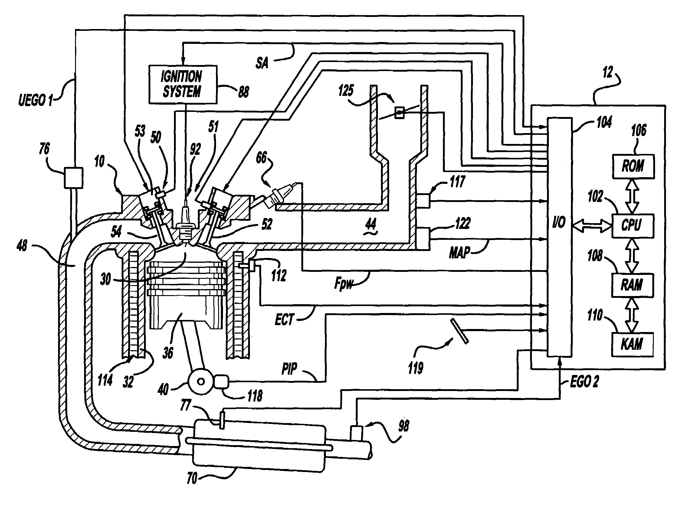
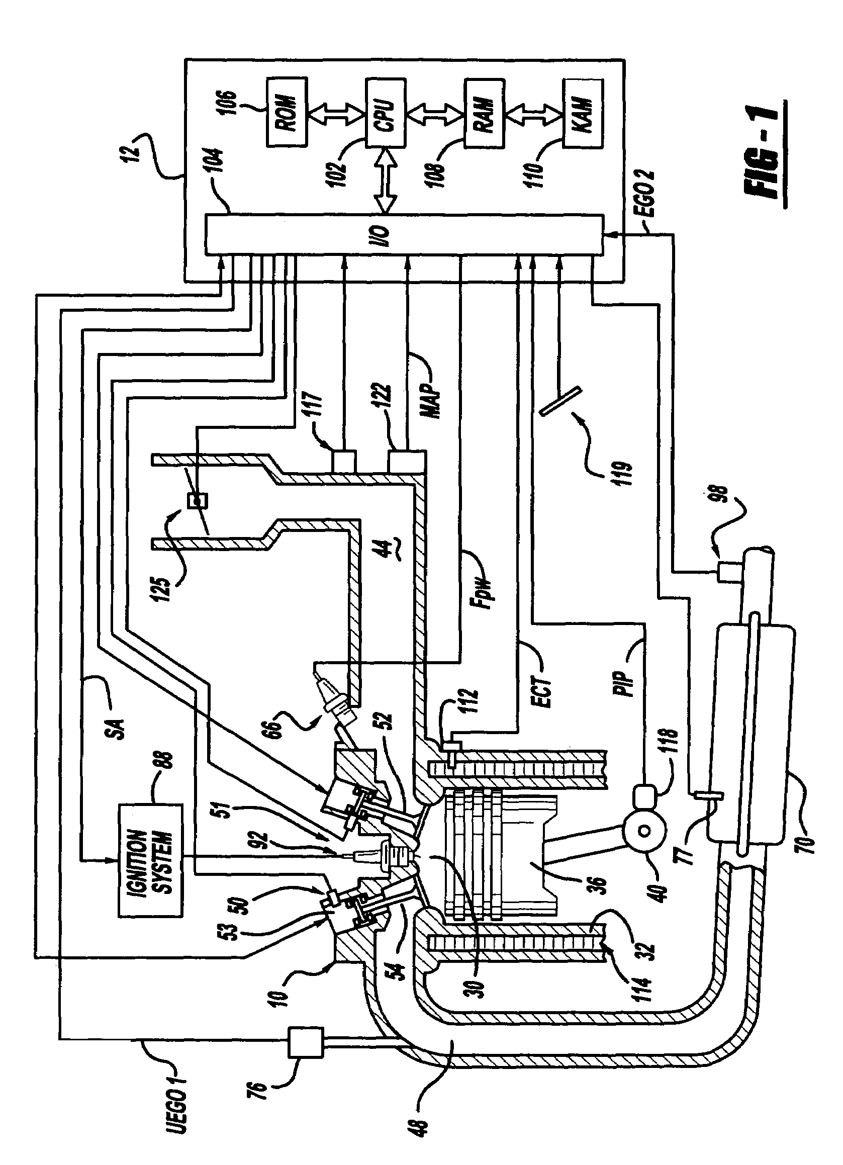
[0078]Referring to FIG. 1, internal combustion engine 10, comprising a plurality of cylinders, one cylinder of which is shown in FIG. 1, is controlled by electronic engine controller 12. Engine 10 includes combustion chamber 30 and cylinder walls 32 with piston 36 positioned therein and connected to crankshaft 40. Combustion chamber 30 is shown communicating with intake manifold 44 and exhaust manifold 48 via respective intake valve 52 an exhaust valve 54. Each intake and exhaust valve is operated by an electromechanically controlled valve coil and armature assembly 53. Armature temperature is determined by temperature sensor 51. Valve position is determined by position sensor 50. In an alternative example, each of valves actuators for valves 52 and 54 has a position sensor and a temperature sensor.

[0079]Intake manifold 44 is also shown having fuel injector 66 coupled thereto for delivering liquid fuel in proportion to the pulse width of signal FPW from controller 12. Fuel is delive...


PUM


Abstract

A system and method to control engine valve timing to during the start of an internal combustion engine. Valves that may be deactivated are controlled in a manner to reduce hydrocarbon emissions during the start of an internal combustion engine.

Description

FIELD[0001]The present description relates to a method for starting an internal combustion engine and more particularly to a method for controlling valves that may be deactivated to improve starting of an internal combustion engine.BACKGROUND AND SUMMARY[0002]Conventional mechanically driven valve trains of internal combustion engines operate the intake and exhaust valves based on the position and profile of lobes on a camshaft. The engine crankshaft is connected to the pistons by connecting rods and to the camshaft by a belt or chain. Therefore, the intake and exhaust valve opening and closing events are based on the crankshaft position. This relationship between the crankshaft position, piston position, and valve opening and closing events determines the stroke of a given cylinder, e.g., for a four stroke engine the intake, compression, power, and exhaust strokes. As a result, engine starting and the first cylinder to fire are affected in part by the camshaft / crankshaft timing rel...

Claims


Application Information

Patent Timeline
Patent Type & Authority Patents(United States)
IPC IPC(8): F02N17/00F02D13/02F01L9/20F02D13/06F02D29/02F02D41/00F02D41/02F02D41/04F02D41/06F02N11/08F02N19/00F02N99/00
CPCB60W10/06F01L9/04F02D13/0215F02D41/0002F02D41/042F02D41/062F02N19/004F02N99/006B60W30/192F01L13/0005F01L2013/001F01L2800/01F02D13/0253F02D13/0257F02D13/06F02D41/0087F02D41/024F02D41/047F02D2013/0292F02D2041/001F02D2041/0012Y02T10/42Y02T10/18B60W20/00Y02T10/12Y02T10/40F01L9/20
Inventor LEWIS, DONALD J.RUSSELL, JOHN D.TRASK, NATEMEGLI, THOMAS W.
Owner FORD GLOBAL TECH LLC
Why Eureka
Try Eureka