Electrode for use in lithium battery and rechargeable lithium battery

a lithium battery and electrode technology, applied in secondary cells, electrochemical generators, cell components, etc., can solve the problems of short circuiting in the internal cavity, alloying negative electrodes failing to provide sufficient cycle characteristics, etc., and achieve excellent charge-discharge cycle characteristics and high charge-discharge capacity

Inactive Publication Date: 2007-03-27
SANYO ELECTRIC CO LTD
View PDF66 Cites 85 Cited by
  • Summary
  • Abstract
  • Description
  • Claims
  • Application Information

AI Technical Summary

Benefits of technology

[0005]It is an object of the present invention to provide a novel electrode which, when used as an electrode of a rechargeable lithium battery, can provide a high charge-discharge capacity and excellent charge-discharge cycle characteristics, and also provide a lithium battery and a rechargeable lithium battery utilizing the novel electrode.
[0007]In the present invention, the thin film composed of the active material is divided into columns by the gaps formed therein and extending in its thickness direction, so that spaces are provided in such a fashion as to surround the columnar portions. These spaces serve to relax a stress caused by expansion and shrinkage of the thin film on charge and discharge and thereby prevent the stress from increasing to the extent that causes falling-off of the thin film from the current collector. Accordingly, the columnar portions can be kept adherent at their bottoms to the current collector.
[0029]In the present invention, it is preferred that the current collector constituent is diffused into the thin film of active material. The diffusion of the current collector constituent into the thin film improves adhesion between the current collector and the thin film. Where the diffusing current collector constituent is an element, such as copper, which does not form an alloy with lithium, the thin film in the diffusion region is less alloyed with lithium and undergoes less expansion and shrinkage during a charge-discharge reaction, so that a stress can be prevented from building up to the extent that may cause the thin film to separate from the current collector.
[0030]Preferably, the concentration of the current collector constituent diffused into the thin film is higher in the vicinity of the current collector and lower at a location closer to the thin film surface. Due to the presence of such a concentration gradient of the current collector constituent, the thin film of active material is subjected to less expansion and shrinkage in the vicinity of the current collector during a charge-discharge reaction, so that a stress can be prevented from building up in the vicinity of the current collector to the extent that may cause the thin film to separate from the current collector. Also, the decreasing concentration of the current collector constituent toward the thin film surface enables a high charge-discharge capacity to remain.
[0031]It is preferred that the current collector constituent, when diffused into the thin film, forms a solid solution, instead of an intermetallic compound, with a component of the thin film. The intermetallic compound, as used herein, refers to a compound which has a specific crystal structure formed via combination of metals in specific proportions. The formation of solid solution, instead of intermetallic compound, of the thin film component and the current collector constituent improves adhesion between the thin film and the current collector, resulting in obtaining the increased charge-discharge capacity.
[0037]In the present invention, an interlayer may be provided between the current collector and the thin film to improve adhesion therebetween. Preferably, such an interlayer may comprise a material which forms an alloy, more preferably a solid solution, with the current collector material and the active material.

Problems solved by technology

The use of metallic lithium for the negative active material, although possible to construct a battery with high energy density per weight and volume, presents a problem that the lithium deposited on charge grows into dendrite which could cause internal short-circuiting.
However, such alloying negative electrodes fail to provide sufficient cycle characteristics since alloys, as electrode active materials, are themselves pulverized on charge and discharge to reduce current-collecting capabilities.

Method used


Image

  • Electrode for use in lithium battery and rechargeable lithium battery
  • Electrode for use in lithium battery and rechargeable lithium battery
  • Electrode for use in lithium battery and rechargeable lithium battery

Examples


experiment 1

Fabrication of Negative Electrode

[0096]A microcrystalline silicon thin film was formed on a rolled copper foil (18 μm thick) by a CVD method, using the rolled copper foil as a substrate, silane (SiH4) as a source gas and a hydrogen gas as a carrier gas. Specifically, the copper foil as a substrate was placed on a heater within a reaction chamber. An interior of the reaction chamber was evacuated by a vacuum evacuator to a pressure of 1 Pa or lower. The silane gas as a source gas and the hydrogen (H2) gas as a carrier gas were introduced via a source gas inlet port. The substrate was heated to 180° C. on the heater. A degree of vacuum was adjusted by the vacuum pumping apparatus to a reaction pressure. An RF power supply was operated to excite a radio frequency wave which is introduced via an electrode to induce a glow discharge. Detailed thin-film forming conditions are listed in Table 1. In Table 1, a volumetric unit, sccm, indicates a volumetric flow rate (cm3 / minute) of a fluid a...

experiment 2

[0112]The procedure used in Experiment 1 to construct the battery A1 was followed, except that an electrolytic copper foil (18 μm thick) was used for the current collector as a substrate. That is, a microcrystalline silicon thin film (about 10 μm thick) was deposited on the electrolytic copper foil to fabricate an electrode a3. Using this electrode, a battery A3 was constructed.

[0113]Also, the rolled copper foil used in Experiment 1 was subjected to a one-minute griding treatment with a #400 or #120 emery paper to provide a ground copper foil. The procedure used in Experiment 1 to construct the battery A1 was followed, except that such a ground copper foil was used for the current collector as a substrate. That is, a microcrystalline silicon thin film (about 10 μm thick) was deposited on the copper foil to fabricate an electrode. The electrode fabricated using the copper foil ground with a #400 emery paper was designated as an electrode a4 and the electrode fabricated using the copp...

experiment 3

[0118]The batteries A1 and A3 respectively constructed in Experiments 1 and 2 were further subjected to a charge-discharge cycle test under the same test conditions as used in the Experiment 1 to measure a 30th-cycle capacity retention rate. The results are shown in Table 4.

[0119]

TABLE 4Battery30th-Cycle Capacity Retention RateA191%A397%

[0120]As can be clearly seen from the results given in Table 4, the batteries A1 and A3 exhibit good capacity retention rates even on the 30th-cycle. Particularly, the battery A3 using the copper foil with a higher value of surface roughness Ra for the current collector exhibits good capacity retention rate.

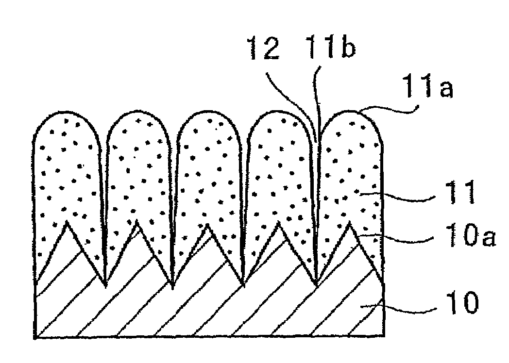
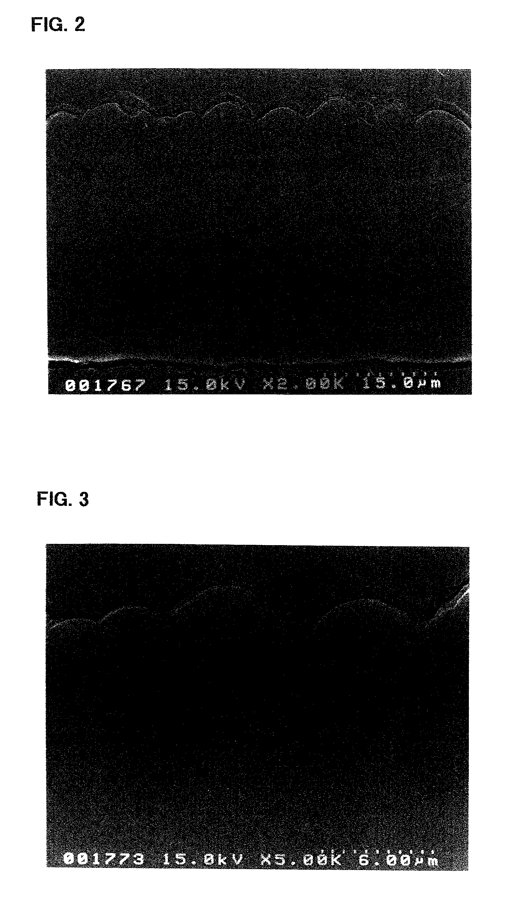
[0121]The electrode a3 incorporated in the battery A3 was viewed under an electron microscope to observe a condition of its silicon thin film. First, the electrode a3 in its state prior to being incorporated in the battery, i.e., before charge and discharge, was observed using a scanning electron microscope. FIGS. 2 and 3 are photomicrographs (sec...


PUM

PropertyMeasurementUnit
surface roughness Raaaaaaaaaaa
roughnessaaaaaaaaaa
roughnessaaaaaaaaaa

Abstract

In an electrode for a lithium battery having a lithium storing and releasing active thin film provided on a current collector, such as a microcrystalline or amorphous silicon thin film, the electrode is characterized in that the thin film is divided into columns by gaps formed therein in a manner to extend in its thickness direction and that the columnar portions are at their bottoms adhered to the current collector.

Description

TECHNICAL FIELD[0001]The present invention relates to a novel electrode for use in lithium battery, a lithium battery and a rechargeable lithium battery utilizing the electrode.BACKGROUND ART[0002]The battery performance of rechargeable lithium batteries recently under intensive research and development, such as charge-discharge voltage, cycle life characteristics or storage characteristics, depends largely upon the types of the electrodes used. This has led to the attempts to better battery performance by improving electrode active materials.[0003]The use of metallic lithium for the negative active material, although possible to construct a battery with high energy density per weight and volume, presents a problem that the lithium deposited on charge grows into dendrite which could cause internal short-circuiting.[0004]Rechargeable lithium batteries are reported (Solid State Ionics, 113–115, p57 (1998)) which use an electrode consisting of aluminum, silicon, tin or the like that is...

Claims


Application Information

Patent Timeline
Patent Type & Authority Patents(United States)
IPC IPC(8): H01M4/58H01M4/00H01M4/66H01M4/139H01M4/131H01M4/133H01M4/134H01M4/1391H01M4/1393H01M4/1395H01M4/36H01M4/38H01M4/40H01M4/70H01M6/10H01M6/40H01M10/05H01M10/052H01M10/0525H01M10/42H01M10/44H01M50/109
CPCH01M4/134H01M4/1395H01M4/366H01M4/40H01M4/661H01M4/667H01M4/70H01M10/052H01M2/0207Y02E60/122H01M4/131H01M4/38H01M4/405H01M4/525H01M4/58H01M6/10H01M6/40H01M10/0587H01M10/44H01M2010/4292H01M4/04H01M4/386H01M4/387Y02E60/10H01M50/109H01M4/139H01M10/0525
Inventor FUJIMOTO, MASAHISAFUJITANI, SHINSHIMA, MASAKIYAGI, HIROMASATARUI, HISAKIKUROKAWA, HIROSHIMATSUTA, SHIGEKIDOMOTO, YOICHIKATO, YOSHIONAKAJIMAIKEDA, HIROAKIASAOKA, KENJIOHSHITA, RYUJI
Owner SANYO ELECTRIC CO LTD
Why Eureka
Try Eureka