Systems and methods for reducing the influence of plasma-generated debris on the internal components of an EUV light source

a technology of plasma-generated debris and internal components, applied in the field of extreme ultraviolet light, can solve the problems of source material debris damaging the optical elements, affecting the operation efficiency of the various plasma chamber optical elements, and generating undesirable by-products in the plasma process

Active Publication Date: 2007-03-27
ASML NETHERLANDS BV
View PDF161 Cites 284 Cited by
  • Summary
  • Abstract
  • Description
  • Claims
  • Application Information

AI Technical Summary

Benefits of technology

[0011]In yet another aspect of an embodiment of the present invention, a system is disclosed for protecting an EUV light source detector surface from plasma generated debris. The system may comprise at least one hollow tube having a tube wall that surrounds a tube lumen, the tube being interposed between a plasma formation site and the detector surface and oriented to prevent at least a portion of the debris directed toward the detector surface from reaching the surface and allowing at least a portion of light generated at the plasma formation site to pass through the lumen and reach the detector surface; and a heater for heating the tube wall to remove debris deposited thereon.

Problems solved by technology

In addition to generating EUV radiation, these plasma processes also typically generate undesirable by-products in the plasma chamber which can include heat, high energy ions and scattered debris from the plasma formation, e.g., atoms and / or clumps of source material that is not fully ionized in the plasma formation process.
These plasma formation by-products can potentially damage or reduce the operational efficiency of the various plasma chamber optical elements including, but not limited to, collector mirrors including multi-layer mirrors (MLM's) capable of EUV reflection at normal incidence and grazing angle incident mirrors, the surfaces of meteorology detectors, windows used to image the plasma formation process, and in the case of LPP, the laser input window.
The heat, high energy ions and / or source material debris may be damaging to the optical elements in a number of ways, including heating them, coating them with materials which reduce light transmission, penetrating into them and, e.g., damaging structural integrity and / or optical properties, e.g., the ability of a mirror to reflect light at such short wavelengths, corroding or eroding them and / or diffusing into them.
For these elements, deposits and heat can combine to fracture (i.e., crack) the element resulting in a loss of vacuum and requiring a costly repair.
Accessing contaminated or damaged optical elements in the plasma chamber for the purpose of cleaning or replacing the elements can be expensive, labor intensive and time-consuming.
In particular, these systems typically require a rather complicated and time consuming purging and vacuum pump-down of the plasma chamber prior to a re-start after the plasma chamber has been opened.
This lengthy process can adversely affect production schedules and decrease the overall efficiency of light sources for which it is typically desirable to operate with little or no downtime.

Method used


Image

  • Systems and methods for reducing the influence of plasma-generated debris on the internal components of an EUV light source
  • Systems and methods for reducing the influence of plasma-generated debris on the internal components of an EUV light source
  • Systems and methods for reducing the influence of plasma-generated debris on the internal components of an EUV light source

Examples


Embodiment Construction

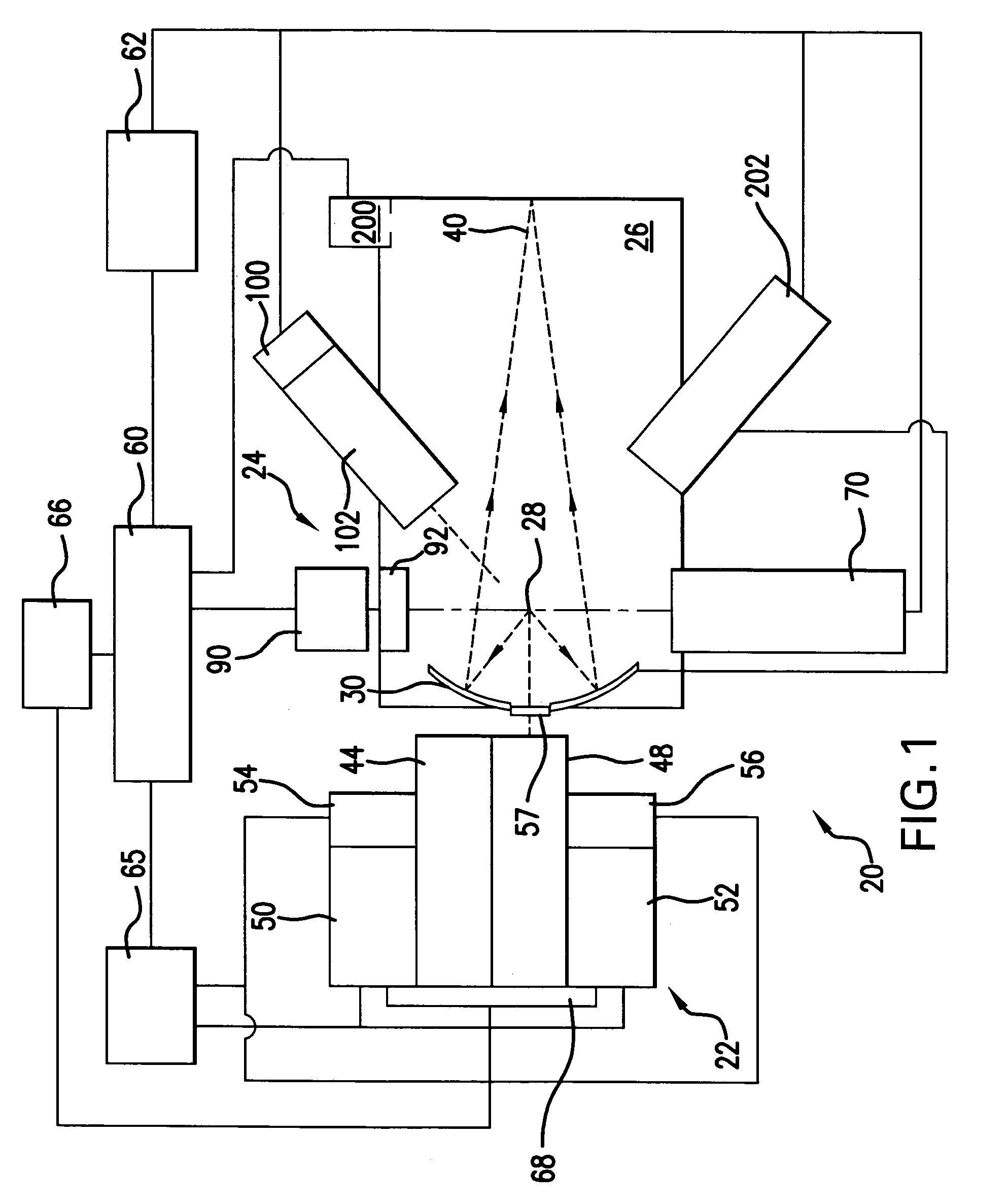
[0022]Turning now to FIG. 1 there is shown a schematic view of an exemplary production EUV light source, e.g., a laser produced plasma EUV light source 20 according to an aspect of the present invention. Although aspects of the present invention are illustrated with reference to a laser produced plasma (LPP), it is to be appreciated that the present invention is equally applicable to other types of light sources which produce a plasma including an electric discharge produced plasma (“DPP”), a representative construction of which is disclosed in co-owned U.S. Pat. No. 6,815,700, which is hereby incorporated by reference.

[0023]Continuing with FIG. 1, an LPP light source 20 may contain a pulsed laser system 22, e.g., a gas discharge exciter or molecular fluorine laser operating at high power and high pulse repetition rate and may be a MOPA configured laser system, e.g., as shown in U.S. Pat. Nos. 6,625,191, 6,549,551, and 6,567,450. The light source 20 may also include a target deliver...


PUM

PropertyMeasurementUnit
wavelengthsaaaaaaaaaa
wavelengthaaaaaaaaaa

Abstract

Systems and methods are disclosed for reducing the influence of plasma generated debris on internal components of an EUV light source. In one aspect, an EUV meteorology monitor is provided which may have a heater to heat an internal multi-layer filtering mirror to a temperature sufficient to remove deposited debris from the mirror. In another aspect, a device is disclosed for removing plasma generated debris from an EUV light source collector mirror having a different debris deposition rate at different zones on the collector mirror. In a particular aspect, an EUV collector mirror system may comprise a source of hydrogen to combine with Li debris to create LiH on a collector surface; and a sputtering system to sputter LiH from the collector surface. In another aspect, an apparatus for etching debris from a surface of a EUV light source collector mirror with a controlled plasma etch rate is disclosed.

Description

CROSS-REFERENCE TO RELATED APPLICATIONS[0001]The present application is a continuation-in-part application of U.S. patent application Ser. No. 10 / 979,945, entitled LPP EUV LIGHT SOURCE, filed on Nov. 1, 2004, and is a continuation-in-part of application of U.S. patent application Ser. No. 10 / 900,839, entitled EUV LIGHT SOURCE, filed on Jul. 27, 2004, and is a continuation-in-part of application of U.S. patent application Ser. No. 10 / 803,526, entitled HIGH REPETITION RATE LPP EUV LIGHT SOURCE, filed on Mar. 17, 2004 now U.S. Pat. No. 7,087,914, and is a continuation-in-part application of U.S. patent application Ser. No. 10 / 798,740, entitled COLLECTOR FOR EUV LIGHT, filed on Mar. 10, 2004, the disclosures of each of which are hereby incorporated by reference herein.FIELD OF THE INVENTION[0002]The present invention relates to extreme ultraviolet (“EUV”) light generators providing EUV light from a plasma created from a source material and collected and directed to a focus for utilizati...

Claims


Application Information

Patent Timeline
Patent Type & Authority Patents(United States)
IPC IPC(8): C25F1/00G03F7/20
CPCB82Y10/00G03F7/70033G03F7/70175H05G2/001G03F7/70916G21K1/06G03F7/7085G21K2201/06H01J2231/50021
Inventor ERSHOV, ALEXANDER I.MARX, WILLIAM F.
Owner ASML NETHERLANDS BV
Why Eureka
Try Eureka