Laser apparatus, laser irradiation method, and manufacturing method of semiconductor device

Inactive Publication Date: 2007-05-29
SEMICON ENERGY LAB CO LTD
View PDF12 Cites 4 Cited by
  • Summary
  • Abstract
  • Description
  • Claims
  • Application Information

AI Technical Summary

Benefits of technology

[0009]The above method has a limit, however, to suppress fluctuation in pressure of a laser medium since it is difficult to accurately generate fluctuation in pressure with the inverted phase in a wave transducer. With respect to excimer laser, fluctuation in energy of an output laser beam is smaller than that of CO2 laser shown in the above Reference 1. The excimer laser is widely used for microfa

Problems solved by technology

The above method has a limit, however, to suppress fluctuation in pressure of a laser medium since it is difficult to accurately generate fluctuation in pressure with the inverted phase in a wave transducer.
Accordingly, in such method as the above method that the fluctuation i

Method used


Image

  • Laser apparatus, laser irradiation method, and manufacturing method of semiconductor device
  • Laser apparatus, laser irradiation method, and manufacturing method of semiconductor device
  • Laser apparatus, laser irradiation method, and manufacturing method of semiconductor device

Examples


embodiment 1

[Embodiment 1]

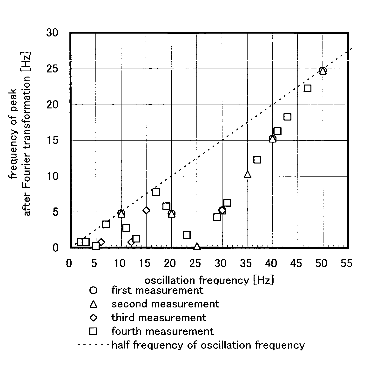
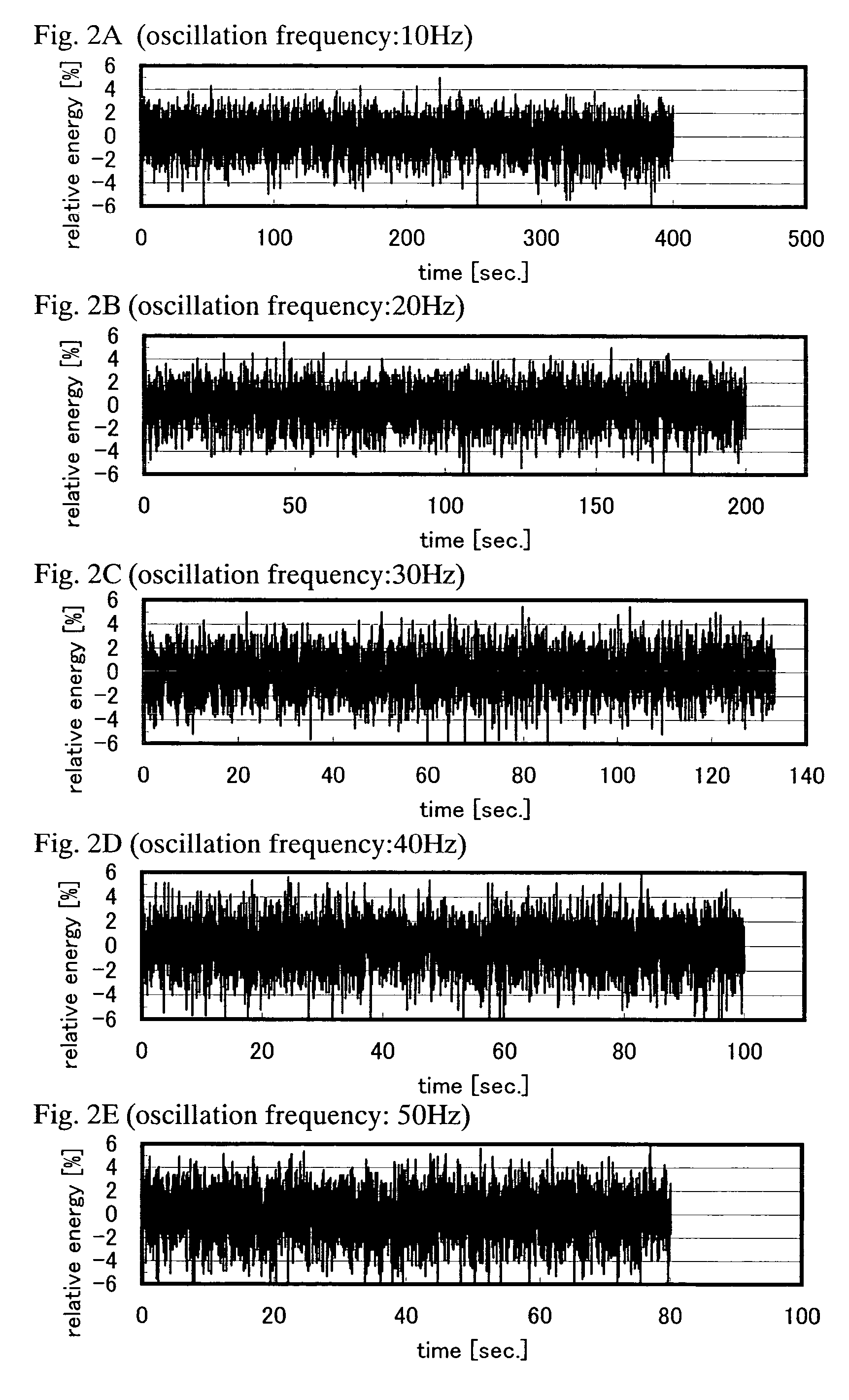
[0072]Periodic fluctuation in energy of a laser beam varies depending on an oscillation frequency of an oscillator. The present embodiment will give a description on the relation between an oscillation frequency of a laser beam emitted from an excimer laser oscillator and a frequency of periodic fluctuation.

[0073]FIG. 6 shows the relation between an oscillation frequency (Hz) of a laser beam and a frequency (Hz) of the highest peak obtained according to Fourier transformation. The horizontal axis indicates the oscillation frequency (Hz), and the vertical axis indicates the position (Hz) of the peak after Fourier transformation. Although measurements have been performed on different days, the same measurement conditions have been used except the oscillation frequency.

[0074]The frequency of the highest peak obtained according to Fourier transformation means the frequency of periodic fluctuation in energy of laser beam. The frequency of the periodic fluctuation repeatedly...

embodiment 2

[Embodiment 2]

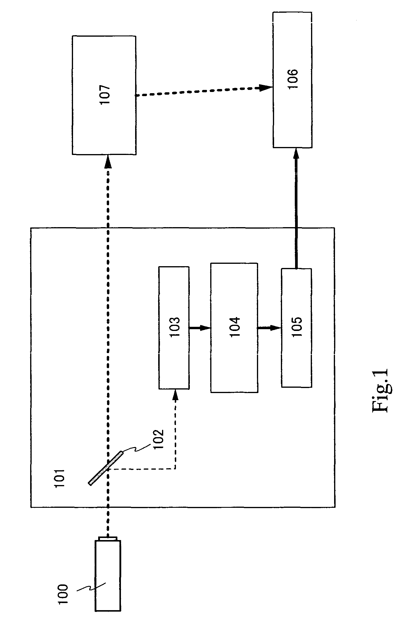
[0080]In the present embodiment, one example of the laser apparatus according to the present invention, shown in Embodiment Mode, will be given.

[0081]FIG. 7 shows a structure of a laser apparatus according to the embodiment. A part of a laser beam emitted from an oscillator 1500 is sampled in an optical system 1502. The sampled laser beam is made to go into a sensor 1503.

[0082]On the other hand, the rest of the laser beam, except the sampled laser beam, is made to go into a beam expander 1504. Although a shutter 1505 for blocking a laser beam is provided between the oscillator 1500 and the beam expander 1504 in the embodiment, it is not always necessary to provide the shutter.

[0083]The beam expander 1504 suppresses expansion of the incident laser beam, and at the same time, the size of a beam spot can be adjusted.

[0084]The laser beam irradiated from the beam expander 1504 is condensed in a beam homogenizer 1506 to have a beam spot with a rectangular, oblong or linear s...


PUM

PropertyMeasurementUnit
Speedaaaaaaaaaa
Frequencyaaaaaaaaaa
Energyaaaaaaaaaa

Abstract

It is an object to provide a laser apparatus, a laser irradiating method and a manufacturing method of a semiconductor device that can perform uniform a process with a laser beam to an object uniformly. The present invention provides a laser apparatus comprising an optical system for sampling a part of a laser beam emitted from an oscillator, a sensor for generating an electric signal including fluctuation in energy of the laser beam as a data from the part of the laser beam, a means for performing signal processing to the electrical signal to grasp a state of the fluctuation in energy of the laser beam, and controlling a relative speed of an beam spot of the laser beam to an object in order to change in phase with the fluctuation in energy of the laser beam.

Description

BACKGROUND OF THE INVENTION[0001]1. Field of the Invention[0002]The present invention relates to a laser apparatus and a laser irradiation method, specially a laser apparatus and a laser irradiation method that have a function of stabilizing energy of an output laser beam. The present invention also relates to a manufacturing method of a semiconductor device including a step for crystallizing a semiconductor film with the laser apparatus and the laser irradiation method.[0003]2. Description of the Related Arts[0004]Lasers are classified into a gas laser and a solid laser according to a laser medium, and have various kinds. In lasers, obtained wavelengths, energy values and pulse characteristics are different depending on the laser mediums, and applications of lasers have been searched according to characteristics of laser beams. Of various lasers, YAG laser, CO2 laser, excimer laser and the like are mainly used for many industrial laser apparatuses.[0005]An excimer laser that is a g...

Claims


Application Information

Patent Timeline
IPC IPC(8): C30B25/12C30B25/14B23K26/08B23K26/42H01L21/00H01S3/00H01S3/13H01S3/225
CPCB23K26/08B23K26/425H01S3/005H01S3/225Y10S117/904B23K26/704
Inventor MIYAIRI, HIDEKAZUSHIMOMURA, AKIHISATAKANO, TAMAEKOYAMA, MASAKI
Owner SEMICON ENERGY LAB CO LTD
Why Eureka
Try Eureka