Bonded structure including a carbon nanotube

a carbon nanotube and bonded structure technology, applied in the direction of fixed capacitor details, natural mineral layered products, cellulosic plastic layered products, etc., can solve the problem of difficult to join a carbon nanotube to an interconnection, a pad or another element, and the requirement for refined processing techniques is more severe, and none of those studies have successfully achieved a high-level control of the size of a tunnel layer or a coulomb island. , to achieve the effect of efficien

Inactive Publication Date: 2007-07-17
SANYO ELECTRIC CO LTD
View PDF13 Cites 17 Cited by
  • Summary
  • Abstract
  • Description
  • Claims
  • Application Information

AI Technical Summary

Benefits of technology

[0011]It is another object of the present invention to provide a nano-device that offers excellent performance and high production efficiency. Also, it is still another object of the present invention to provide an ultrafine interconnection necessary for constituting an integrated circuit composed of nano-devices.
[0059]In the present invention, the polymer may be a membrane protein. Since many of the membrane proteins have a hydrophobic region, employing a membrane protein permits efficient adsorption thereof to a rounded surface of the carbon nanotube, to thereby achieve a stable wrapping. Consequently, it becomes possible to stably manufacture a bonded structure having a desired shape or constitution, or a nano-device provided with such bonded structure.

Problems solved by technology

However a rounded surface of a carbon nanotube has a stable hexagonal ring structure which is not chemically active in general, so it is difficult to join a carbon nanotube to an interconnection, a pad or another element.
Also, when it comes to designing a quantum-effect nano-device in which a quantum effect of a single electron transistor etc. is utilized, the requirement for the refined processing technique is more severe.
Studies on the single electron transistor have so far been aggressively performed as observed in the JP-A (laid open) No. 2001-77346 and JP-A (laid open) H9-69630, however nearly none of those studies have successfully achieved a high-level control of a size of a tunnel layer or a Coulomb island, to thereby make full use of the characteristics obtainable from the quantum effect.

Method used


Image

  • Bonded structure including a carbon nanotube
  • Bonded structure including a carbon nanotube
  • Bonded structure including a carbon nanotube

Examples


first embodiment

[0088]A bonded structure according to this embodiment includes at least two carbon nanotube-based structures, each constituted of a carbon nanotube with its rounded surface wrapped with a polymer and provided with a receptor or a ligand immobilized as a bonding material on the wrapping on a carbon nanotube-based structure, joined to each other via a specific interaction between the receptor and the ligand.

[0089]The carbon nanotube-based structure employed in the bonded structure of this embodiment is constituted of a carbon nanotube and a polymer wrapping a rounded surface thereof. The wrapping may be provided on a certain region of a surface of the carbon nanotube, or uniformly formed all over the rounded surface of the carbon nanotube. Also, the wrapping may be a tight layer closely formed all over a circumferential surface at a certain region on the rounded surface of the carbon nanotube.

[0090]In this carbon nanotube-based structure, the polymer may be wound around a rounded surf...

second embodiment

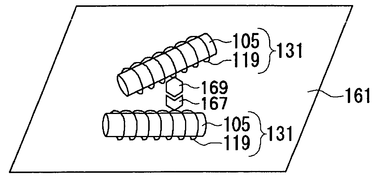
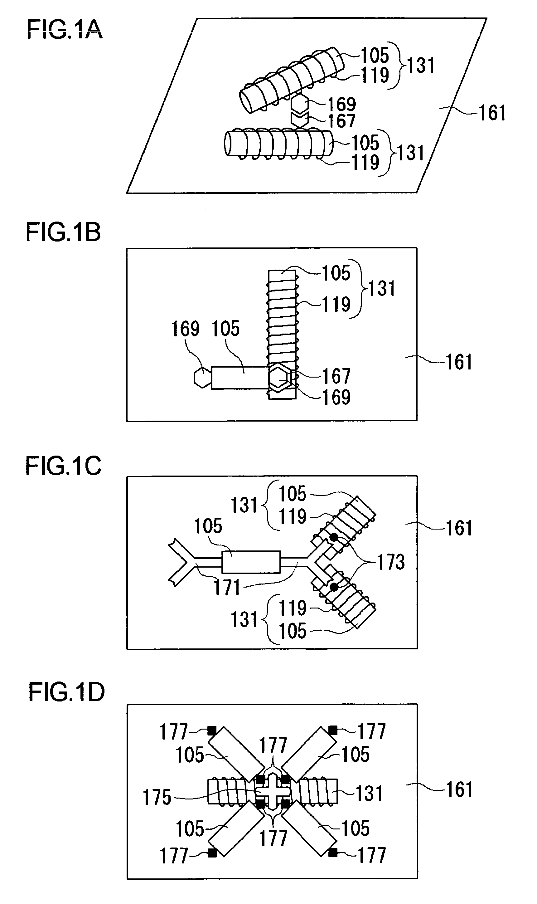
[0137]This embodiment relates to a bonded structure constituted of a carbon nanotube-based structure and a carbon nanotube not wrapped with a polymer joined to each other. FIG. 1B is a plan view showing a bonded structure according to this embodiment. A method of manufacturing the bonded structure shown in FIG. 1B will be described hereunder referring to FIGS. 2A through 3D and FIGS. 5A and 5B, focusing on aspects different from the first embodiment.

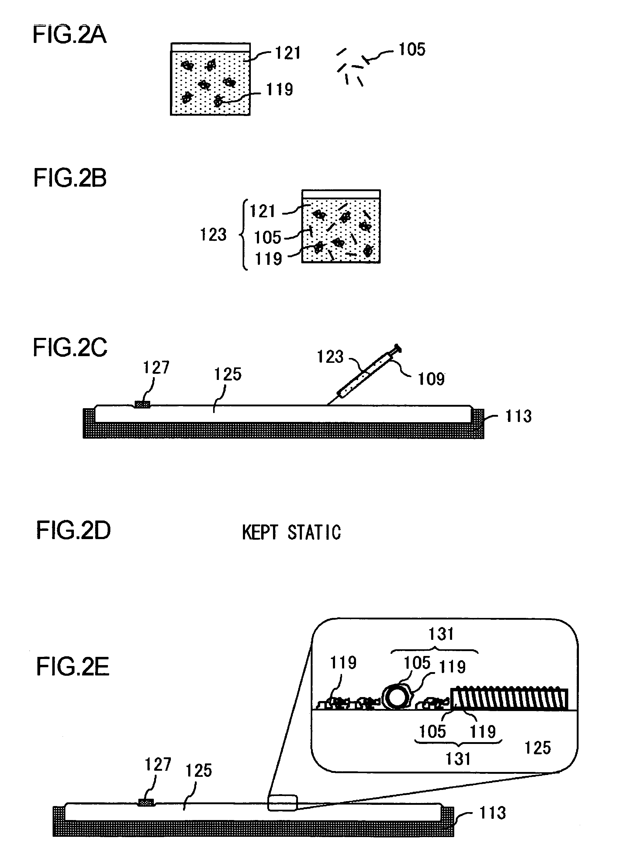
[0138]The receptor 167 is immobilized on the carbon nanotube-based structure 131 on the substrate 161 through the steps of FIGS. 2A through 3D as in the first embodiment (FIG. 3D).

[0139]Then the carbon nanotube 105 having the ligand 169 immobilized thereon is added to the buffer solution 163 filled over the substrate 161 provided with the carbon nanotube-based structure 131 having the receptor 167 immobilized on the surface thereof (FIG. 5A). Because of a specific interaction between the receptor 167 immobilized on the carbon nanotube-ba...

third embodiment

[0144]This embodiment relates to a method of bonding a carbon nanotube-based structure on a substrate. FIG. 7 is a schematic drawing of a bonded structure according to this embodiment. In this drawing, the carbon nanotube-based structure 131 is selectively adsorbed on a surface of gold 179 provided on a base member (not shown in the drawings), via a thiol group included in the polymer 119.

[0145]In this embodiment, the polymer 119 is constituted of a substance described in the first embodiment, to which for example a thiol group is introduced. Otherwise, a polymer including a thiol group may be employed as it is. Referring to the base member, a material provided with for example the gold 179 on a part or an entirety of the surface thereof can be used. A material provided with the gold 179 can selectively adsorb the thiol group included in the polymer 119 to its surface.

[0146]The bonded structure of FIG. 7 is manufactured as follows. As in the first embodiment, the carbon nanotube-bas...


PUM

PropertyMeasurementUnit
thicknessaaaaaaaaaa
diameteraaaaaaaaaa
diameteraaaaaaaaaa

Abstract

A technique of stably bonding a structure including a carbon nanotube with another structure is to be provided. Also, a nano-device that offers excellent performance and high production efficiency is to be provided.A polymer and a carbon nanotube are dispersed in a dispersion medium and on a filled liquid in a Langmuir trough, to obtain a carbon nanotube-based structure constituted of a carbon nanotube and the polymer wound around its rounded surface. The carbon nanotube-based structure is adhered to a substrate, and a ligand is immobilized on a side chain of the polymer. A receptor is immobilized on another carbon nanotube-based structure, and the both carbon nanotube-based structures are joined because of a specific interaction between the ligand and the receptor.

Description

[0001]This application is based on Japanese patent applications No. 2003-4970, No. 2003-4971, No. 2003-428385, and No. 2003-428402, the content of which is incorporated hereinto by reference.BACKGROUND OF THE INVENTION[0002]1. Field of the Invention[0003]The present invention relates to a bonded structure provided with a carbon nanotube, and to an interconnection, a single electron transistor and a capacitor in which a carbon nanotube is incorporated.[0004]2. Description of the Related Art[0005]Recently, nano-devices have been very actively developed based on the so-called nano-processing technique. A nano-device can be operated merely by several electrons, therefore power consumption can be significantly reduced in comparison with a conventional silicon-based device, besides an element size can be dramatically diminished.[0006]For the development of such nano-device, introduction of a carbon nanotube is being intensively studied. A carbon nanotube is constituted of cylindrically co...

Claims


Application Information

Patent Timeline
Patent Type & Authority Patents(United States)
IPC IPC(8): B32B5/16B32B9/00H01G4/228H01L21/20H01L51/00
CPCB82Y10/00B82Y30/00H01G4/228H01L21/2007H01L51/0048H01L51/0049H01L51/0595Y10T428/25Y10S977/748Y10S977/745Y10S977/746Y10T428/2998Y10T428/2991H10K85/225H10K85/221H10K10/701
Inventor SUGIYAMA, YUKIHIROOUE, YASUHIRO
Owner SANYO ELECTRIC CO LTD
Why Eureka
Try Eureka