Apparatus for delivering, repositioning and/or retrieving self-expanding stents

a technology for self-expanding stents and apparatuses, which is applied in the field of apparatus for delivering, repositioning and/or retrieving self-expanding stents, can solve the problems of stents being buried completely in the vessel wall, bes being less flexible than self-expanding stents, and less capable of being delivered through tortuous vessels. achieve the effect of enabling the precise positioning of the sten

Inactive Publication Date: 2007-08-21
INTEK TECH
View PDF40 Cites 216 Cited by
  • Summary
  • Abstract
  • Description
  • Claims
  • Application Information

AI Technical Summary

Benefits of technology

[0038]Another object of the present invention is to provide new and improved apparatus for delivering self-expanding stents to desired locations in body vessels by which the stent can be deployed in a controlled gradual manner to thereby enhance the accuracy of positioning.
[0049]In accordance with another aspect of the invention, the catheter assembly includes a capturing device for releasably coupling the stent to the catheter assembly during deployment, as well as for grasping an already-deployed stent for purposes of retrieval and / or repositioning. The capturing device prevents the stent from being carried away by the bloodstream or from migrating on the catheter, and is also structured and arranged to assist in drawing the stent in its flexible and pliable condition into the catheter assembly for repositioning and retrieval.

Problems solved by technology

It eventually results in formation of a neointima, which coats the stent and buries it completely in the vessel wall.
Most BES are less flexible than self-expanding stents and are therefore less capable of being delivered through tortuous vessels and, when a BES is deployed in a tortuous vessel, it often straightens the vessel, forcing the vessel to conform to the shape of the stent rather than vice versa.
This generally results in portions of the stent not being completely apposed to the vessel wall which in turn affects endothelialization and overall patency rate.
If shape recovery occurs at body temperature, no heating or cooling is necessary during the delivery and deployment, provided delivery is relatively speedy.
If, however, a tortuous iliac anatomy or other interference delays prompt deployment of a nitinol stent with these characteristics, premature warming to body temperature could cause expansion in the delivery sheath, increase friction, and interfere with delivery.
However, while SES are preferable relative to BES in many applications with respect to achieving optimized endothelialization and increased patency rates, currently available arrangements for delivering and deploying SES are not entirely satisfactory.
It has generally not been possible to deploy SES in the correct desired location in a vessel as precisely as in the case of BES with currently available delivery arrangements for the reason that the temperature of the SES rapidly increases to body temperature upon withdrawal of the outer sheath and therefore the stent quickly expands into engagement with the vessel wall.
Consequently, there is not always enough time to finely adjust the position of the SES as it quickly expands, and it is not uncommon for the distal end of an SES, which is exposed to body temperature first, and which therefore expands before the rest of the SES, to engage and become attached to the vessel wall in the wrong position and in turn inhibit or prevent further adjustments in the position of the SES in the vessel.
Another drawback in conventional arrangements for delivering and deploying SES, as compared to BES, is that during deployment while BES are advantageously pressed against the vessel wall with a relatively large outward force by the dilating balloon in the manner of an angioplasty to insure attachment of the BES to the vessel wall, SES must rely solely on the outward force exerted by the expanding SES to provide initial attachment.
Still another drawback in conventional arrangements for delivering and deploying SES is the possibility that when delivery is protracted, the SES is exposed to body temperature inside the delivery system.
The deployment process can then become more difficult—the device may open abruptly after being freed from the system and may “jump” beyond the target as the SE expands during deployment.
BES cannot be repositioned or retrieved after deployment and while arrangements have been proposed for enabling the repositioning and / or retrieval of SES formed of two-way shape memory material, no practical workable arrangement has been developed.
Yet a disturbingly high 15% to 20% of the procedures fail within six months, due to the aggressive neointimal proliferation.
A damaged blood cell initiates a chemical cascade, which results in clot formation.
Therefore an exposed bare metallic stent carries a risk of inducing thrombus formation within it.
However, to date, no satisfactory method or apparatus is available for obtaining a controlled gradual deployment of an SES without stent migration, or for repositioning and / or retrieving a SES.
While arrangements have been suggested in the prior art for delivering SES to a correct location in a precise manner and for repositioning and retrieving SES formed of two-way shape memory material, these prior art arrangements all have drawbacks and have not been adopted in practice.
This technique appears to be clinically impractical and not safe due to high risk of potential tissue and blood cell damage.
For the stent retrieval, a radio frequency current within the range of 50 to 2,000 kHz must be applied directly to the stent to provide partial collapse of the stent after it is heated to a temperature above 43° C. to 90° C. However, if the transition temperature of the stent material is in the range of 43° C.-90° C., the radial force of the device will be greatly reduced at the body temperature of 37° C., and may not be sufficient for therapeutic effect.
Heating of the stent to almost a boiling temperature can cause irreversible damage to vascular wall and blood coagulation.
The connecting wire can traverse the entire body if the stent is placed in the coronary or carotid artery from the femoral approach, increasing risk of thrombus formation around the wire and distal embolization, thrombosis of the femoral artery and infection of the inquinal region.
However, the stent with inwardly extending engagement members will likely require a larger delivery system than regular tubular devices.
Any manipulation of the catheters and guidewires in the stented area may potentially accidentally engage the hooks of the stent with its subsequent dislodgment and damage of, the vessel.
The hooks extending into the vessel lumen will cause turbulence of blood flow around them, leading to activation of the coagulation system and thrombus formation.
This stent is designed for predominant use in the human urethra and is not suitable for cardiovascular applications due to very large metal surface that could be thrombogenic and increased size of the delivery system.
This technique could be too traumatic for cardiovascular applications.
The recovery apparatus will likely have a large profile, making this method not practical or feasible for percutaneous use in blood vessels or other tubular organs.
As discussed above, heating of the stent to a temperature over 80° C. could be unsafe, especially with intravascular injection of hot fluid.
Use of external radio frequency irradiation will cause heating not only of the stent, but all tissues from the skin surface to the stented vessel deep inside the body and beyond.
Cooling the stent to below the freezing temperature by injection of a very cold fluid into a blood circulation for removal is also impractical and not feasible in a real clinical setting.

Method used


Image

  • Apparatus for delivering, repositioning and/or retrieving self-expanding stents
  • Apparatus for delivering, repositioning and/or retrieving self-expanding stents
  • Apparatus for delivering, repositioning and/or retrieving self-expanding stents

Examples


first embodiment

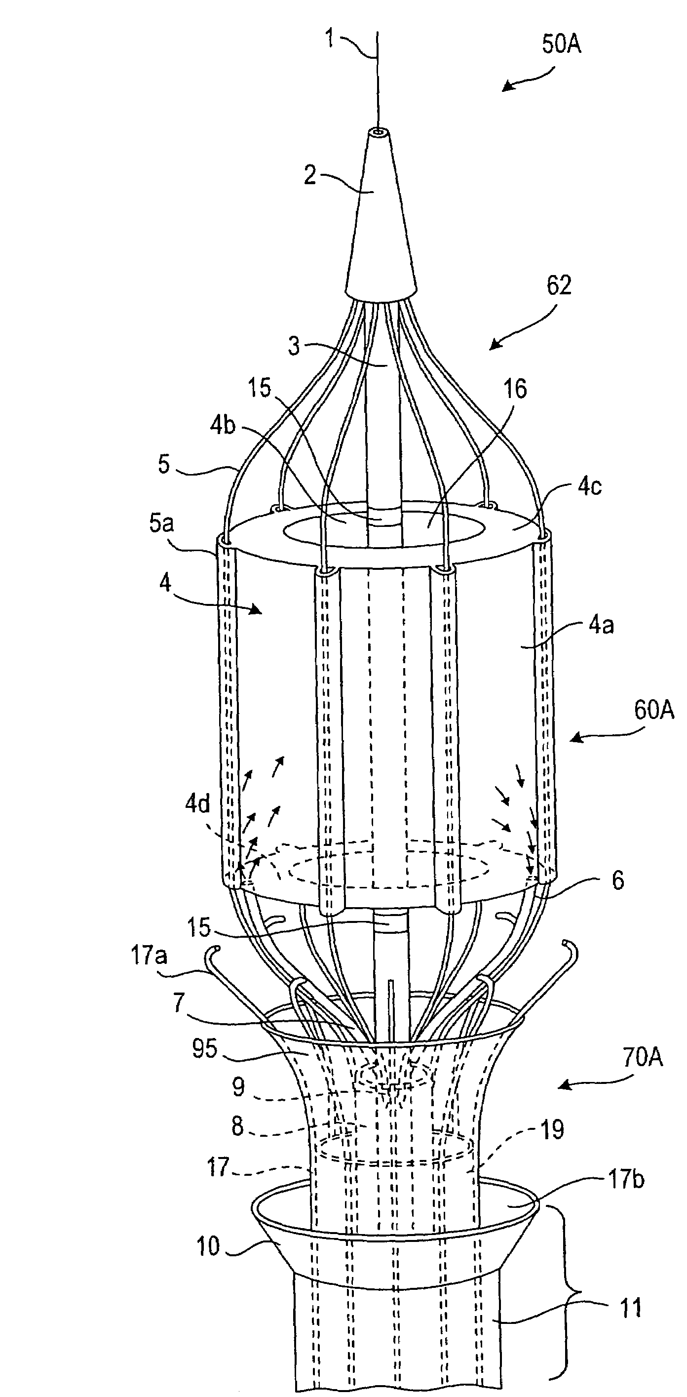
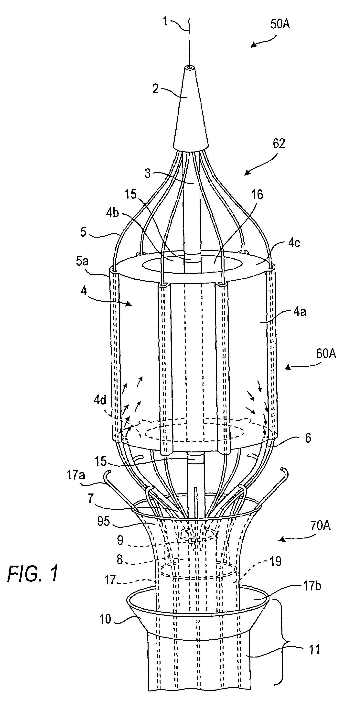
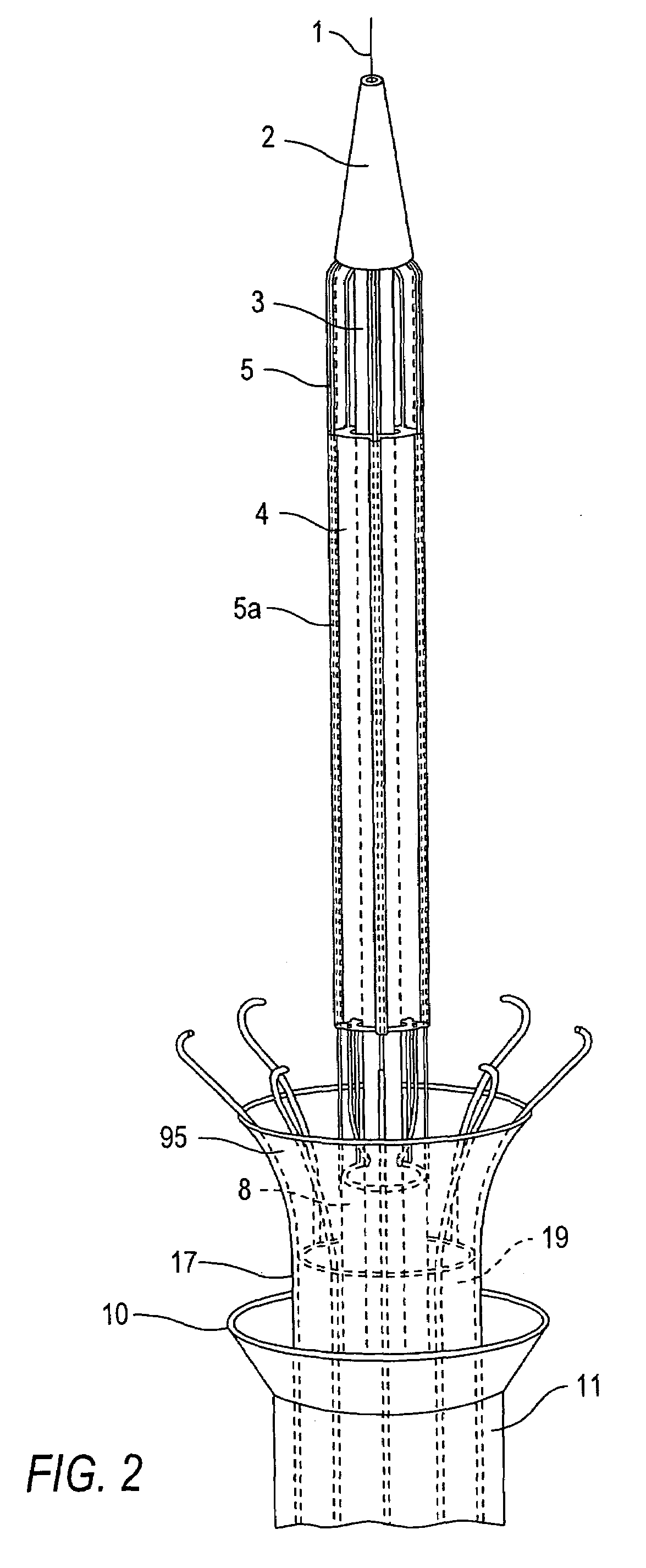
[0107]Referring now to the drawings in which like reference characters designate identical or corresponding parts throughout the several views, and more particularly to FIGS. 1-3, apparatus in accordance with the invention comprises a catheter assembly 50A (only the distal end region of which is shown), a thermal transfer device 60A connected to catheter assembly 50A and an associated stent capturing device 70A. Catheter assembly 50A comprises a low profile outer core catheter 8, having an inner movable core catheter 3, an inner stent-capturing sheath 19 situated over the outer core catheter 8, and an outer stent-receiving sheath 11. In this embodiment, the thermal transfer device 60A comprises a frame assembly 62 to which an expandable balloon 4 is connected. Balloon 4 has a sleeve-type configuration, i.e., the balloon 4 has an annular cross-section along its entire length. As discussed below, this shape is advantageous since the flow of blood or other body fluid which normally occ...

second embodiment

[0120]A modification of the second version of the second embodiment is shown in FIG. 8a, where the frame wires 5 are paired and interconnected with a single bridging bar 98 in their central portions. The stent-capturing sheath 19 with the capturing hooks are eliminated in this modification. Instead, there are at least four capturing wires 96, which are molded to the inner core catheter 3 at the base of conus 2. The capturing wires 96 extend parallel to the frame wires 5, but outside the balloon 12 and pass under the bridging bars 98 between the central portions of the paired frame wires 5. The relative motion of the movable core 3 and the outer core catheter 8 promotes opening and closing of the capturing wires 96. When the balloon 12 is expanded, capturing wires 96 open with it. When the balloon is slowly deflated, the capturing wires 96 stay open and do not follow the collapsing balloon until the angled portion of the capturing wires become engaged with the bridging bars 98, which...

third embodiment

[0133]Referring to FIGS. 13-16, a first version of apparatus in accordance with the invention comprises a thermal transfer device 60C associated with a catheter assembly 50C and including a stent capturing device 70C. The thermal transfer device 60C comprises an inflatable and collapsible balloon 20 formed of the same type of material as that from which balloons 4 and 12 are made. The balloon 20 has a cloverleaf configuration in the cross sectional view (FIG. 14a). Balloon sectors 201-204 merge with each other at the proximal and distal ends of the balloon (FIG. 14 and FIG. 15) and in the center of the balloon define radial spaces 201-4, 201-2, 202-3 and 203-4 between them (FIG. 14a). Each of the radial spaces are formed by a pair of opposed radially and axially extending wall members 94 extending between the outer wall of balloon 20 and the inner core catheter 3. The distal end of the balloon is attached to the inner core catheter 3 at the attachment of the cone 2 and the proximal ...


PUM


Abstract

Apparatus for delivering and deploying a stent formed of a shape memory alloy to a desired position in a tubular area of the body, and / or for repositioning and / or retrieving a stent formed of a two-way shape memory alloy. An arrangement is provided by which the temperature of the stent is locally adjusted during delivery, repositioning and / or retrieval in a safe and controlled manner by engagement with an expandable and collapsible thermal transfer member situated on a catheter assembly.

Description

[0001]This Application is a divisional of prior application Ser. No. 09 / 845,098, filed Apr. 27, 2001, now U.S. Pat. No. 6,676,692.FIELD OF THE INVENTION[0002]The present invention generally relates to advanced medical endoluminal devices and methods of minimally invasive treatment of blockages of the blood vessels and other tubular organs. More particularly, the present invention relates to apparatus for delivering, repositioning and / or retrieving self-expanding stents for internal reinforcing of diseased tubular structure and / or for local delivery of pharmacological or radioactive agents having a beneficial advantage of reduction of re-stenosis.BACKGROUND OF THE INVENTION[0003]Reference is made to a related application entitled Methods for Delivery Repositioning and / or Retrieving Self-Expanding Stents filed concurrently with this application.[0004]A stent is a generally longitudinal cylindrical device formed of biocompatible material, such as a metal or plastic, which is used in th...

Claims


Application Information

Patent Timeline
Patent Type & Authority Patents(United States)
IPC IPC(8): A61F2/06A61F2/00A61F2/84
CPCA61F2/95A61B17/221A61F2/958A61F2002/9528A61F2002/9534A61F2210/0023A61B2017/22035A61B2017/2215
Inventor RABKIN, DMITRYMORAG, EYALPERELSON, OPHIR
Owner INTEK TECH
Why Eureka
Try Eureka