Selective glass batching methods for improving melting efficiency and reducing gross segregation of glass batch components

a batching method and glass technology, applied in glass furnaces, glass making apparatus, manufacturing tools, etc., can solve the problems of increasing the tendency of batch segregation, borates showing similar problems, and the effort of batch mixing, so as to improve the melting efficiency

Active Publication Date: 2007-08-28
ALFRED UNIVERSITY
View PDF18 Cites 13 Cited by
  • Summary
  • Abstract
  • Description
  • Claims
  • Application Information

AI Technical Summary

Benefits of technology

[0022]It is an object of the present invention to overcome the drawbacks associated with the conventional glass batching and melting methods. Particularly, it is an object of the present invention to provide a method for selectively pre-combining certain components of a glass batch recipe prior to introducing the overall batch composition into a furnace melting tank to control the melting reactions (i.e., reaction paths) within the tank in order to improve melting efficiency.
[0023]In conjunction with improved melting efficiency, it is also an object of the present invention to facilitate decreased energy usage, reduce the need for chemical fining agents that contribute to air pollutants and raw material cost, decrease pollution and ultimately produce higher quality, lower cost glass products, and reduce gross segregation of raw material batch constituents during melting.

Problems solved by technology

The formation of this eutectic liquid, however, can increase the tendency for batch segregation and effectively reverse the efforts of batch mixing.
Similar reactions occur in container glass compositions, and in the case of fiber-glass production, borates exhibit similar problems in the initial stages of melting.
This segregation process leads to the formation of large-scale domains, or agglomerates, of nearly pure silica that then require excessively long residence times for dissolution into the surrounding liquid melt.
Moreover, the phenomenon of large-scale batch segregation in the melter tank is commonly seen in finished glass in the form of defects such as stones, which are mostly composed of undissolved quartz; seeds, which are bubbles that are not liberated from the melt during fining; and cord lines, which are optical distortions caused by local differences in composition.
These defects are direct evidence of off-composition glass due to batch de-mixing or incomplete re-mixing that decrease the overall material efficiency and reduce the quality of the final product.
Despite the fact that batch segregation in the glass tank and the potential defects that can result therefrom are recognized in the industry, and despite a long felt need to reduce this undesirable behavior and improve melting efficiency and overall quality, the glass industry has not yet successfully addressed these issues with a viable commercial solution.
While some mixing and fining is required to remove gaseous bubbles, the expensive and energy intensive processes to improve the mixing of the molten batch can also be attributed to large scale segregation of batch materials.
As described above, however, the uncontrolled production of low viscosity liquids during the melting process contributes to undesirable batch segregation.
Although a melt that fosters lower viscosities overall may improve quartz dissolution and diffusion rates during melting, these benefits can only be achieved after the highest melting point batch components are sufficiently melted and any batch agglomerates are fully reacted in the melt.
Another problem with conventional glass making technology lies in the amount of energy required to maintain a continuous glass melting operation, and the environmental impact of the use of fossil fuel to provide this energy.

Method used


Image

  • Selective glass batching methods for improving melting efficiency and reducing gross segregation of glass batch components
  • Selective glass batching methods for improving melting efficiency and reducing gross segregation of glass batch components
  • Selective glass batching methods for improving melting efficiency and reducing gross segregation of glass batch components

Examples


example

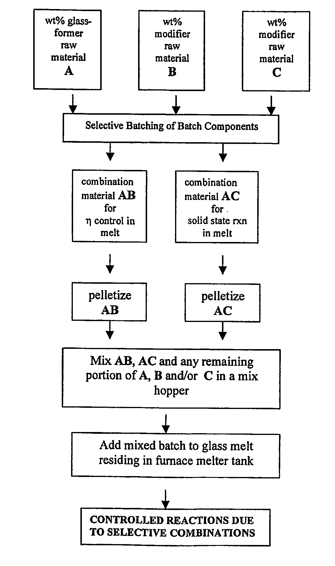
[0078]The following example is particularly directed to a float glass composition and melting scenario. FIG. 8 is a flow diagram illustrating the selective batching method according to the example. Traditional batch components of Na2CO3, CaCO3, and SiO2 are provided. Instead of simply mixing all of these raw material components together, however, specific combinations of these raw materials are selectively pre-batched.

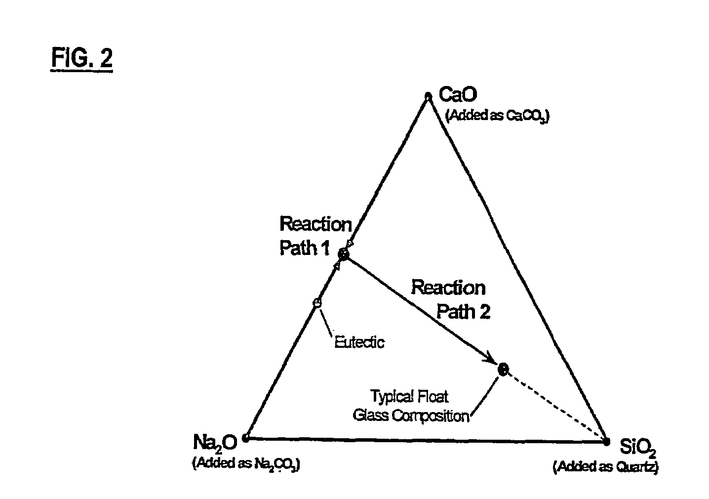
[0079]That is, Na2CO3 is selectively batched with quartz in the eutectic proportions of the Na2O-SiO2 system to provide a first combination material to minimize the possibility of low viscosity liquid formation by preventing the eutectic reaction of Na2CO3 with other raw materials (such as CaCO3) that ordinarily occurs absent the selective batching according to the present invention. CaCO3 is selectively combined and pre-reacted with quartz to form a second combination material (i.e., an intermediate reaction product). In this case, the second combination material is w...


PUM

PropertyMeasurementUnit
temperatureaaaaaaaaaa
viscosityaaaaaaaaaa
viscosityaaaaaaaaaa

Abstract

A method of controlling reaction paths of glass batch components added to a resident glass melt is provided, including the steps of providing a plurality of raw material batch components according to a batch recipe, selectively combining a portion of the batch components into a first combination material having a melting temperature in a range of 60 to 90% of a resident melt temperature (K) and a viscosity3 a melt viscosity / 100, and selectively combining another portion of the batch components into a second combination material having a reaction temperature in a range of 60 to 100% of the resident melt temperature, the second combination material being capable of forming an intermediate compound via a solid state reaction before reacting with the glass melt. The first and second combination materials and any remaining batch components are mixed and introduced into a glass melter.

Description

FIELD OF THE INVENTION[0001]The present invention relates to selective batching methods in general and more particularly, to selectively combining particular constituents of a glass batch composition before introducing the batch to the melt in order to reduce the tendency for gross segregation of batch components in the melt and to improve melting efficiency by controlling thermal reaction paths.BACKGROUND OF THE INVENTION[0002]Conventional glass batching processes are illustrated as a flow diagram in FIG. 1. Typical glass batching usually involves transferring raw materials directly from storage silos into a weigh hopper, weighing the raw materials according to a weight percent (wt %) batch recipe, adding a specified amount of cullet, and mixing the raw batch and the cullet in a large scale mixer. In some cases, the mixer itself functions as a final check-scale for the batch recipe. From the mixer, the mixed batch materials are transferred to one or more hoppers positioned adjacent...

Claims


Application Information

Patent Timeline
Patent Type & Authority Patents(United States)
IPC IPC(8): C03B3/00C03B35/00C03B5/00C03B5/16C03B5/18C03B1/02C03C1/00C03C1/02
CPCC03B1/02C03B3/02C03C1/026C03C1/002Y02P40/57
Inventor CARTY, WILLIAM M.
Owner ALFRED UNIVERSITY
Why Eureka
Try Eureka