
Laser peening process and apparatus using a liquid erosion-resistant opaque overlay coating

a technology of opaque overlay coating and laser peening process, which is applied in the direction of laser beam welding apparatus, welding apparatus, manufacturing tools, etc., can solve the problems of high explosive materials, inability to meet some industrial needs, and inability to use high pressure gases in extreme environments, so as to reduce the need for thickness control measures, improve thickness uniformity, and facilitate displacement

Inactive Publication Date: 2007-09-11
LSP TECH INC
View PDF8 Cites 12 Cited by
  • Summary
  • Abstract
  • Description
  • Claims
  • Application Information

AI Technical Summary

Benefits of technology

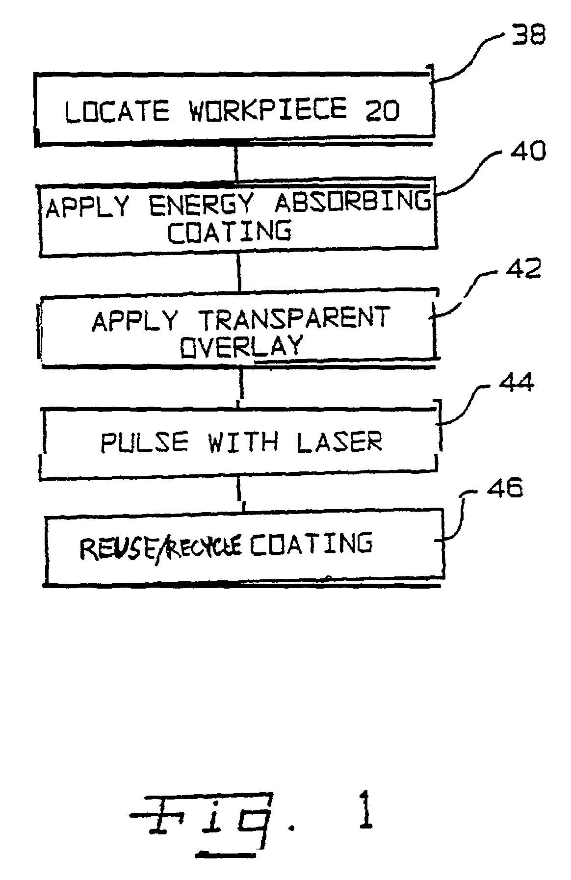
[0017]An advantage of the present invention is that the method allows the use of energy-absorbing coating that is viscous, adherent, and resistant to drying and that lends itself to reuse / recycling. Prior laser painting processes utilized oil, water or acrylic based paints that needed to be dried prior to use and that did not lend themselves to reuse and / or recycling.
[0018]Another advantage of the present invention is that the energy-absorbing coating that has an appropriate viscosity that allows it to both conform to a workpiece shape under substantially static conditions and be readily displaced under sufficiently dynamic conditions. Alternately, the energy-absorbing material can be chosen so as to be self-limiting with respect to its thickness, thereby improving thickness uniformity and reducing the need for thickness control measures.
[0019]Yet another advantage of the present invention is that since the energy-absorbing coating (both the viscous and self-limiting thickness versions) is resistant to drying and is typically oil based (i.e., lubricant as base), such a coating material will not tend to stop up an applicator, either during use or after an extended period of stagnation therewith in. The use of extremely fine or colloidal particulate prevents clogging of the applicator and prevents problems with settling during storage or processing. The non-drying feature permits the pre-application of the energy-absorbing coating. This pre-application can reduce the time and amount of spraying needed to be done in the processing cell and can limit the opportunity of applying a laser pulse to an uncoated area.
[0020]A further advantage of the present invention is the utilization of a flowing, transparent water overlay for processing of the workpiece surface. The use of the flowing water covers the coated area uniformly while additionally ensuring that any heat possibly transferred to the workpiece by the process will be removed.
[0021]Yet a further advantage of the present invention is that the process eliminates the need to move the workpiece from workstation to workstation as was previously accomplished and necessitated. The laser shock processing system now can be adapted to manufacturing process workloads and requirements.
[0022]A yet additional advantage of the present invention is that the applicator(s) in the coating system can be fitted with integral protectors that can preclude unwanted spraying of selected workpiece portions and / or selected process apparatus components, thereby both eliminating the need to manually mask such selected portions / components and reducing clean-up time.

Problems solved by technology

For example: (a) it is difficult and costly to shock process non-planar surfaces and complicated geometries, (b) storage and handling of the high explosive materials and high pressure gases pose a hazard, (c) the processes are difficult to automate and thus fail to meet some industrial needs and (d) high explosive materials and high pressure gases cannot be used in extreme environments such as high temperatures and high vacuum.
However, the depth of treatment using conventional shot peening is typically only 0.004 to 0.006 inches deep.
This depth is only 10–20 percent as deep as achieved with laser peening, and the surface enhancement of material properties with shot peening is much less effective.
Additionally, it is easy to shock the workpiece repetitively.
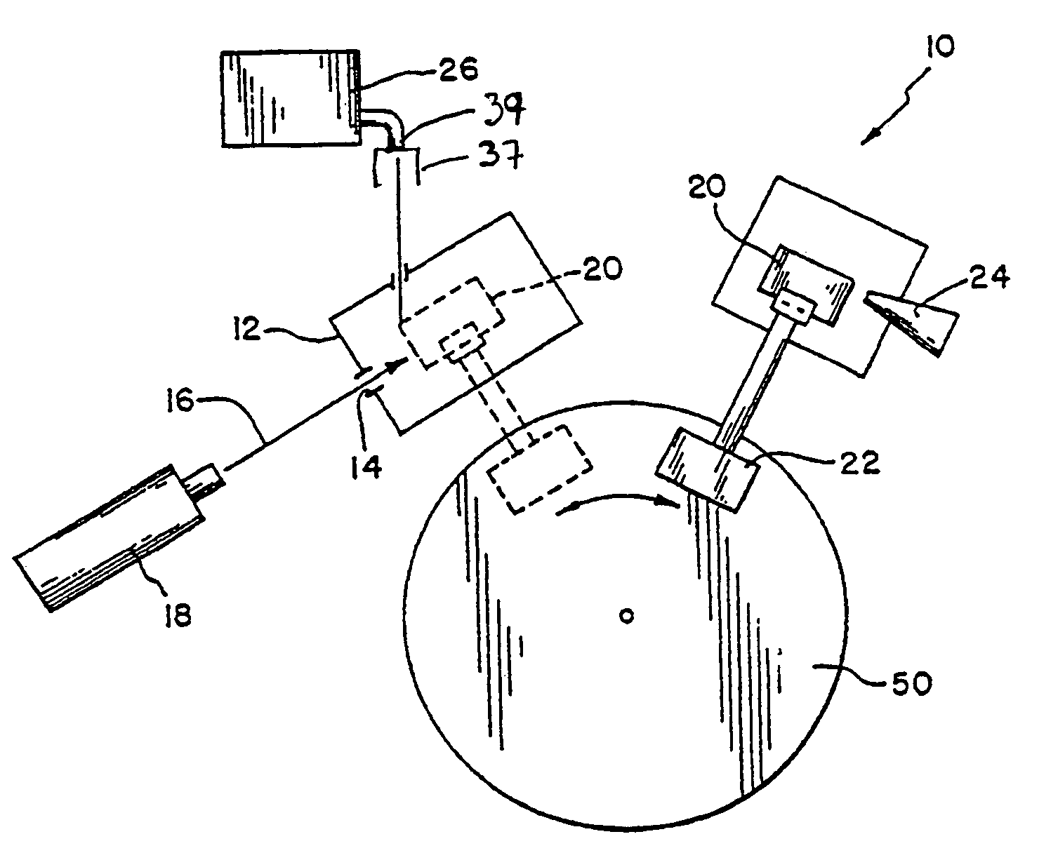
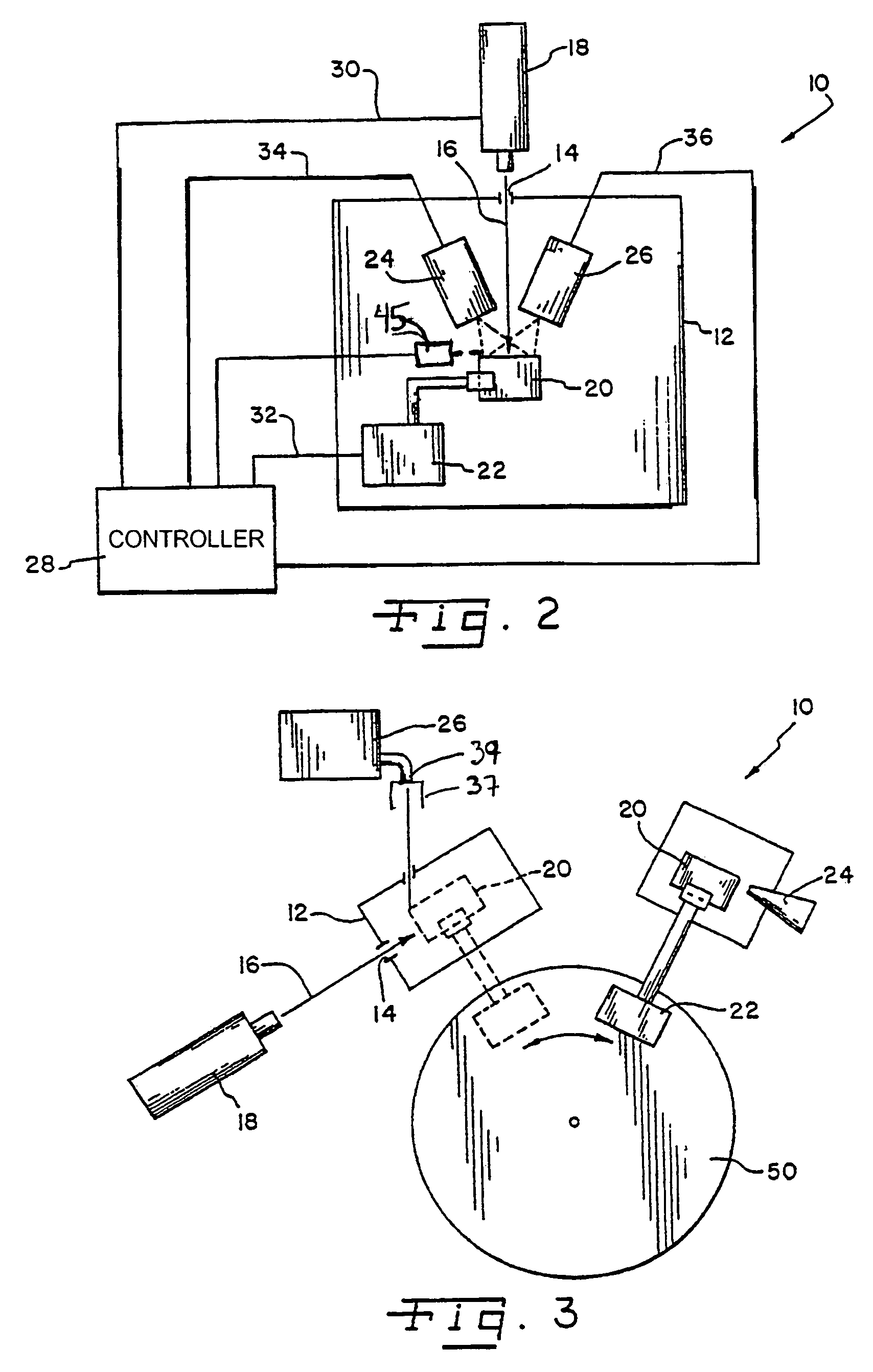
During processing, a laser beam is directed to pass through the water overlay and is absorbed by the opaque overlay (black paint or tape), causing a rapid vaporization of the opaque overlay surface and the generation of a high-amplitude shockwave.
In a similar manner, re-application of tape to overcome the problem of tape damage from the laser shot during processing adds significantly to the processing time and cost.
Other drawbacks have been found to be associated with using paints, both oil-based and water-based ones.
These drawbacks stem from the need to dry paint prior to use thereof.
As such, recycling and / or reuse of paints is not practical, given typical removal methods.
The opaque overlays used tend to be eroded by the transparent overlay during processing and have resulted in the generation of a weaker shockwave than achieved with tape or dry paint.

Method used


Image

  • Laser peening process and apparatus using a liquid erosion-resistant opaque overlay coating
  • Laser peening process and apparatus using a liquid erosion-resistant opaque overlay coating
  • Laser peening process and apparatus using a liquid erosion-resistant opaque overlay coating

Examples


Embodiment Construction

[0028]The improvements in fatigue life produced by laser shock processing are the results of residual compressive stresses developed in the irradiated surface that retard fatigue crack initiation and / or slow the crack propagation rate. A crack front is the leading edge of a crack as it propagates through a solid material. Changes in the shape of a crack front and slowing of the crack growth rate when the crack front encounters the laser shock zone in a laser shock processing condition have been shown.

[0029]Laser shock processing is an effective method of increasing fatigue life in metals by treating fatigue critical regions. As to what effect the tensile residual stresses surrounding the laser shocked region would have on crack initiation, a previous study is described in “Shockwaves and High Strained Rate Phenomena in Metals” by A. H. Clauer, J. H. Holbrook and B. P. Fairand, ed. by M. S. Meyers and L. E. Murr, Plenum Press, New York (1981), pp. 675–702. Described in the above refe...


PUM

PropertyMeasurementUnit
depthaaaaaaaaaa
thickaaaaaaaaaa
transparentaaaaaaaaaa

Abstract

The invention relates to a method and apparatus for improving properties of a solid material by providing shockwaves there through. Laser shock processing is used to provide the shockwaves. The method includes applying a liquid energy-absorbing overlay, which is resistant to erosion and dissolution by the transparent water overlay and which is resistant to drying to a portion of the surface of the solid material and then applying a transparent overlay to the coated portion of the solid material. A pulse of coherent laser energy is directed to the coated portion of the solid material to create a shockwave. Advantageously, at least a portion of the unspent energy-absorbing overlay can be reused in situ at a further laser treatment location and / or recovered for later use.

Description

BACKGROUND OF THE INVENTION[0001]1. Field of the Invention[0002]The present invention relates to the use of coherent energy pulses, as from high power pulsed lasers, in the shock processing of solid materials, and, more particularly, to methods and apparatus for improving properties of solid materials by providing shockwaves therein. The invention is especially useful for enhancing or creating desired physical properties such as high cycle fatigue life, fretting fatigue life, hardness, strength, and fatigue strength.[0003]2. Description of the Related Art[0004]Old methods for the shock processing of solid materials typically involve the use of high explosive materials in contact with the solid, high explosive materials or high pressure gases used to accelerate a plate that strikes the solid to produce shockwaves therein. Such methods have several disadvantages. For example: (a) it is difficult and costly to shock process non-planar surfaces and complicated geometries, (b) storage an...

Claims


Application Information

Patent Timeline
Patent Type & Authority Patents(United States)
IPC IPC(8): B23K26/00B23K26/18C21D10/00
CPCB23K26/0069B23K26/009C21D10/005B23K26/18B23K26/356
Inventor TENAGLIA, RICHARD D.DULANEY, JEFF L.LAHRMAN, DAVID F.
Owner LSP TECH INC
Learn More