
Atomic layer deposition for turbine components

a technology of atomic layer and turbine components, which is applied in the direction of machines/engines, superimposed coating processes, natural mineral layered products, etc., can solve the problems of affecting the operation of the turbine, the ceramic layer cannot be extended, and the thermal expansion cannot be accommodated. , to achieve the effect of reducing the risk of atomization, and reducing the thermal expansion ra

Inactive Publication Date: 2007-10-23
HONEYWELL INT INC
View PDF32 Cites 35 Cited by
  • Summary
  • Abstract
  • Description
  • Claims
  • Application Information

AI Technical Summary

Benefits of technology

The present invention relates to a method for coating a ceramic thermal barrier coating on a superalloy component, which involves depositing a tantalum oxide layer and an inorganic layer on the surface of the component using atomic layer deposition. The ceramic coating has a unique structure with gaps and columns, which results in improved thermal insulation and reduced oxidation. The inorganic layer is deposited conformally over the gaps and has a uniform thickness. The method can be used to protect the component from high temperatures and corrosion in gas turbine engines. The invention also provides a method for coating a silicon-based substrate with a tantalum oxide layer and an inorganic layer using atomic layer deposition. The invention also includes a method for coating a substrate with a thermal barrier coating that has a unique structure with gaps and columns.

Problems solved by technology

However, the ability to operate at these increasing temperatures is limited by the ability of the superalloy turbine blades and vanes to maintain their mechanical strength when exposed to the heat, oxidation, and corrosive effects of the impinging gas.
A problem with columnar-grained ceramic layers is that when exposed to temperatures over 1100 degrees C.
Once the gaps become closed, the ceramic layer can no longer accommodate the thermal expansion and may spall or crack.
The same problem also exists in plasma sprayed TBC, in which the pores and gaps in the typical laminar structure are sintered at use temperatures.
In addition, sintering of the TBC increases the thermal conductivity of the coating, which is undesirable, since the thermal insulation property of the coating degrades and the temperature in the substrate increases.
Frequent maintenance of turbine components is required due to the tendency for sintering of the TBC which causes the TBC to spall or crack and increase thermal conductivity.
However, coating methods in the manner of the prior art tend to produce a coating that does not conform to the topography of the columnar grains.
This can significantly reduce the effectiveness of the sintering inhibiting property of the coating.
Another problem associated with the prior art coating on the top portion of the TBC is the thermal expansion and modulus mismatch created by the inhomogeneous distribution of the coating, which can shorten the bonding life of the TBC on the substrate.
Another major problem with a common TBC, such as a TBC containing ZrO2, HfO2 and Ta2O5, is poor oxidation barrier properties.
These materials have the strong tendency to be in non-stoichiometric quantities with oxygen deficient structure.
Because of this poor oxygen diffusion barrier property, a TBC containing ZrO2, HfO2, or Ta2O5 is not effective at all in protecting the substrate from oxidation at high temperatures.
However, even the bonding coat cannot sustain the oxidation attack for long, and a common failure mechanism of TBC is directly due to the formation and growth of thermally grown alumina due to oxidation at the interface between the substrate and the TBC.
The prior art is not specifically intended for high performance applications under extreme conditions, and some suffer from one or more of the following disadvantages:a) non-conformity of coating layers.b) inability to sustain high temperature conditions.c) increased spalling and cracking.d) subject to excessive oxygen diffusion.

Method used


Image

  • Atomic layer deposition for turbine components
  • Atomic layer deposition for turbine components
  • Atomic layer deposition for turbine components

Examples


Embodiment Construction

[0027]The following detailed description is of the best currently contemplated modes of carrying out the invention. The description is not to be taken in a limiting sense, but is made merely for the purpose of illustrating the general principles of the invention, since the scope of the invention is best defined by the appended claims.

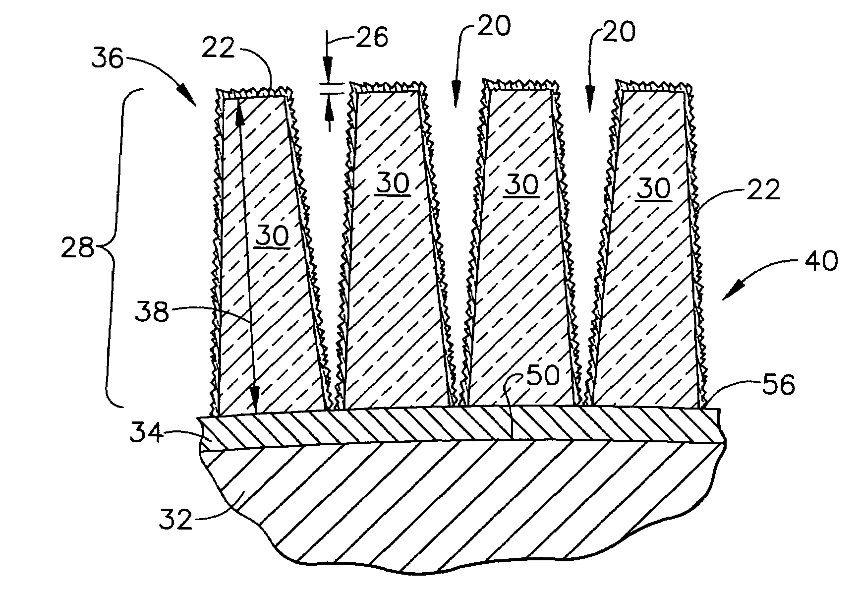
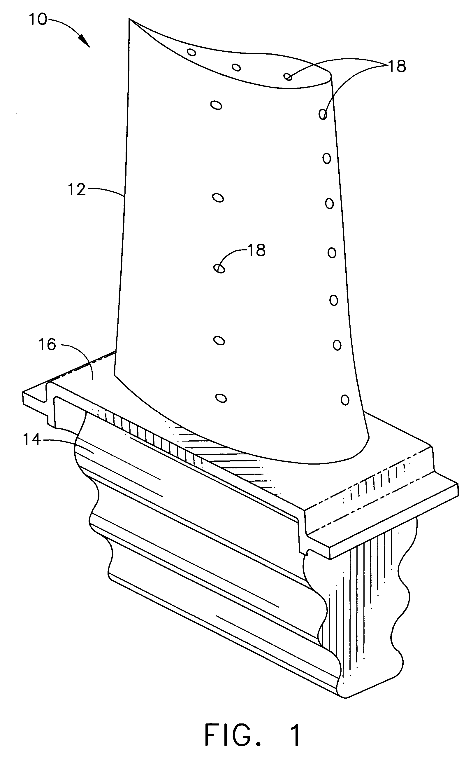
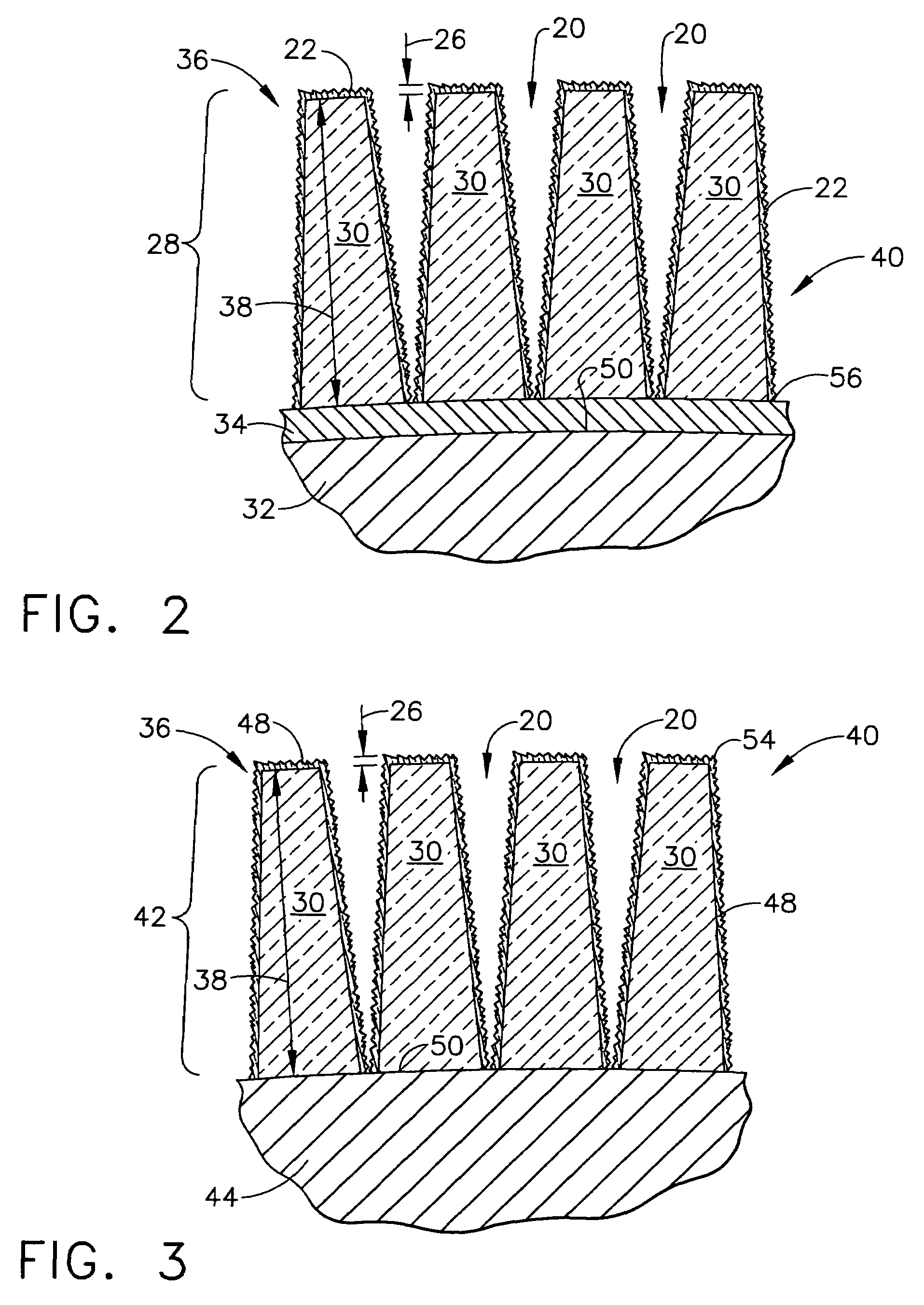
[0028]The present invention is generally applicable to components that operate within environments characterized by relatively high temperatures (e.g., temperatures in excess of about 1100 degrees C.), and are therefore subjected to severe thermal stresses and thermal cycling. Notable examples of such components include the high and low pressure turbine nozzles and blades, shrouds, vanes, combustor liners, combustor fuel nozzles, combustor shields, and augmentor hardware of gas turbine engines. One such example is the turbine blade 10 shown in FIG. 1. The turbine blade 10 generally includes an airfoil 12 against which hot combustion gases may be directe...


PUM

PropertyMeasurementUnit
thicknessaaaaaaaaaa
thicknessaaaaaaaaaa
thicknessaaaaaaaaaa

Abstract

A method and superalloy component for depositing a layer of material onto gas turbine engine components by atomic layer deposition. A superalloy component may have a ceramic thermal barrier coating on at least a portion of its surface, comprising a superalloy substrate and a bonding coat; and aluminum oxide (Al2O3) layer may be deposited on top of an yttria-stabilized zirconia layer and form a bonding coat by atomic layer deposition. The yttria-stabilized zirconia layer may have a plurality of micron sized gaps extending from the top surface of the ceramic coating towards the substrate and defining a plurality of columns of the yttria-stabilized zirconia layer. Also, atomic layer deposition may be used to lay an aluminum oxide (Al2O3) layer over a tantalum oxide (Ta2O5) layer on a silicon-based substrate. Using atomic layer deposition to coat the gas turbine engine components permits conformal coating of the columnar surface to permit gap expansion and contraction without sintering of the columnar surface or spalling of the coating, and form an oxidation resistant bonding coat.

Description

BACKGROUND OF THE INVENTION[0001]This invention relates generally to thermal barrier and environmental barrier coatings for metallic and ceramic substrates and in particular to thermal barrier coatings and environmental barrier coatings that are resistant to sintering and oxidation damage for components in gas turbine engines.[0002]As gas turbine engine technology advances and engines are required to be more efficient, gas temperatures within the engines continue to rise. However, the ability to operate at these increasing temperatures is limited by the ability of the superalloy turbine blades and vanes to maintain their mechanical strength when exposed to the heat, oxidation, and corrosive effects of the impinging gas. One approach to this problem has been to apply a protective thermal barrier coating (TBC) or environmental barrier coating (EBC) which insulates the blades and vanes from higher gas temperatures and hot gas corrosion, and to apply an interfacial bonding coat between ...

Claims


Application Information

Patent Timeline
Patent Type & Authority Patents(United States)
IPC IPC(8): C23C14/30C23C16/32C23C16/34C23C16/36C23C16/40C23C16/42B32B15/04C23C16/455C23C28/04C23C30/00F01D5/28
CPCC23C16/403C23C16/45555C23C28/3215C23C28/34C23C28/345C23C28/3455C23C30/00F01D5/284F01D5/288C23C28/341C23C28/321C23C28/325C23C28/42C23C16/45525Y10T428/12576F05D2230/31F05D2230/313Y10T428/12611Y10T428/2462Y10T428/12597
Inventor LI, CHIEN-WEI
Owner HONEYWELL INT INC
Learn More