Anisotropic thin-film rare-earth permanent magnet

Inactive Publication Date: 2007-10-23
SUMITOMO SPECIAL METAL CO LTD
View PDF15 Cites 9 Cited by
  • Summary
  • Abstract
  • Description
  • Claims
  • Application Information

AI Technical Summary

Benefits of technology

[0009]As a result of extensive research into the high magnet characteristics of thin-film rare-earth permanent magnets, the inventors discovered that the residual magnetic flux density can be markedly increased by layering one or a plurality of atomic layered units in which a monoatomic layer based on a rare-earth element is layered on a substrate of a nonmagnetic material, and a plurality of monoatomic layers of a transition metal element are then layered, whereby each unit has an axis of easy magnetization in the layering direction, and the percentage content of the transition metal element in relation to the rare-earth element is increased.
[0010]In add

Problems solved by technology

The crystal structures of the layered formations obtained by these methods are disadvantageous in that the axis of easy magnetization is random, isotropic permanent magnet characteristics alone can be obtained in terms of magnetic characteristics, and only magnetic characteristics that are vastly inferior to those of anisotropic sintered permanent magnets can be obtained.
This method is disadvantageous in that the c axis, which is the axis of easy magnetization in Nd Fe B, is very difficult to completely align in the layering direction because the growth direction varies with the crystal directi

Method used


Image

  • Anisotropic thin-film rare-earth permanent magnet
  • Anisotropic thin-film rare-earth permanent magnet

Examples


example 1

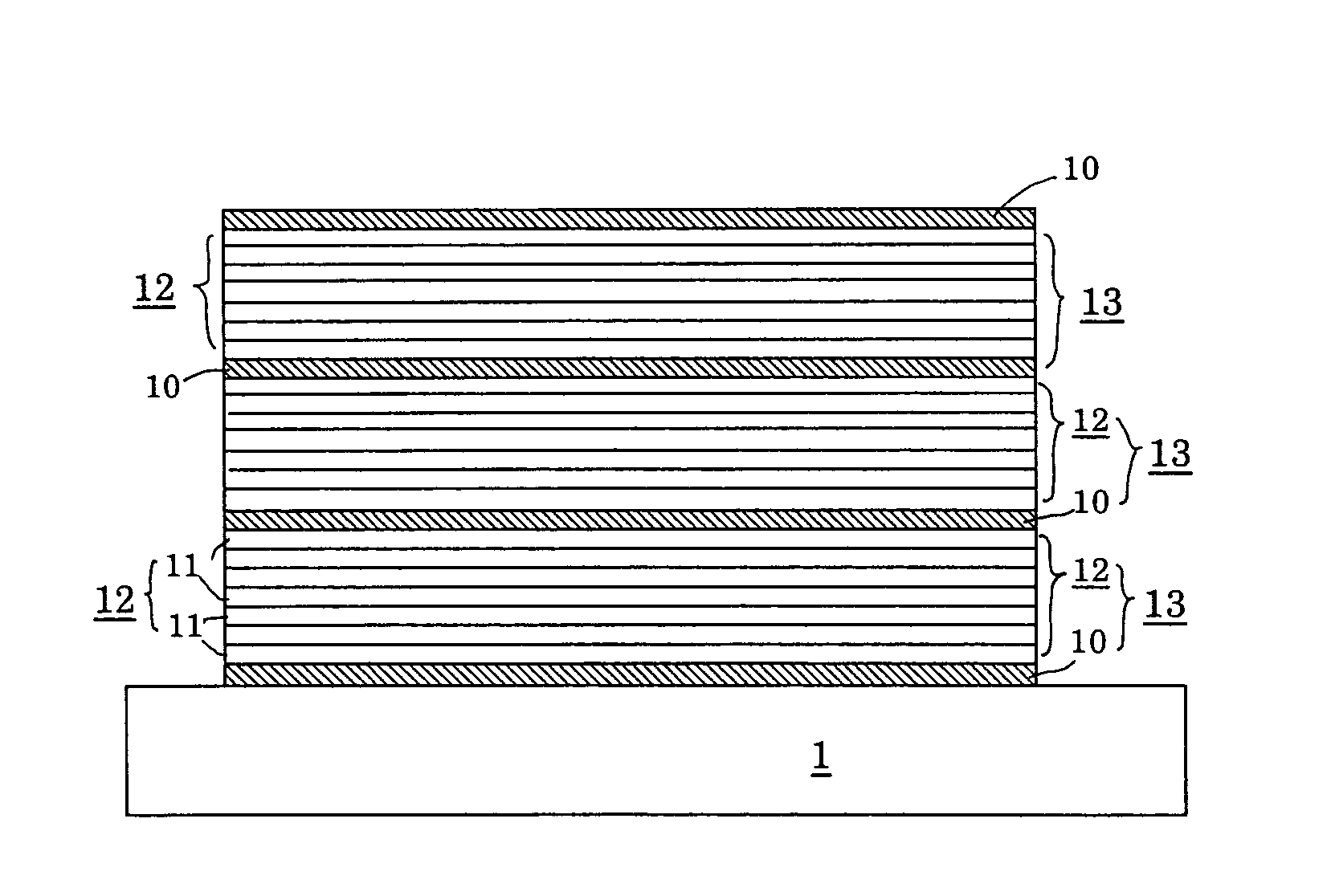
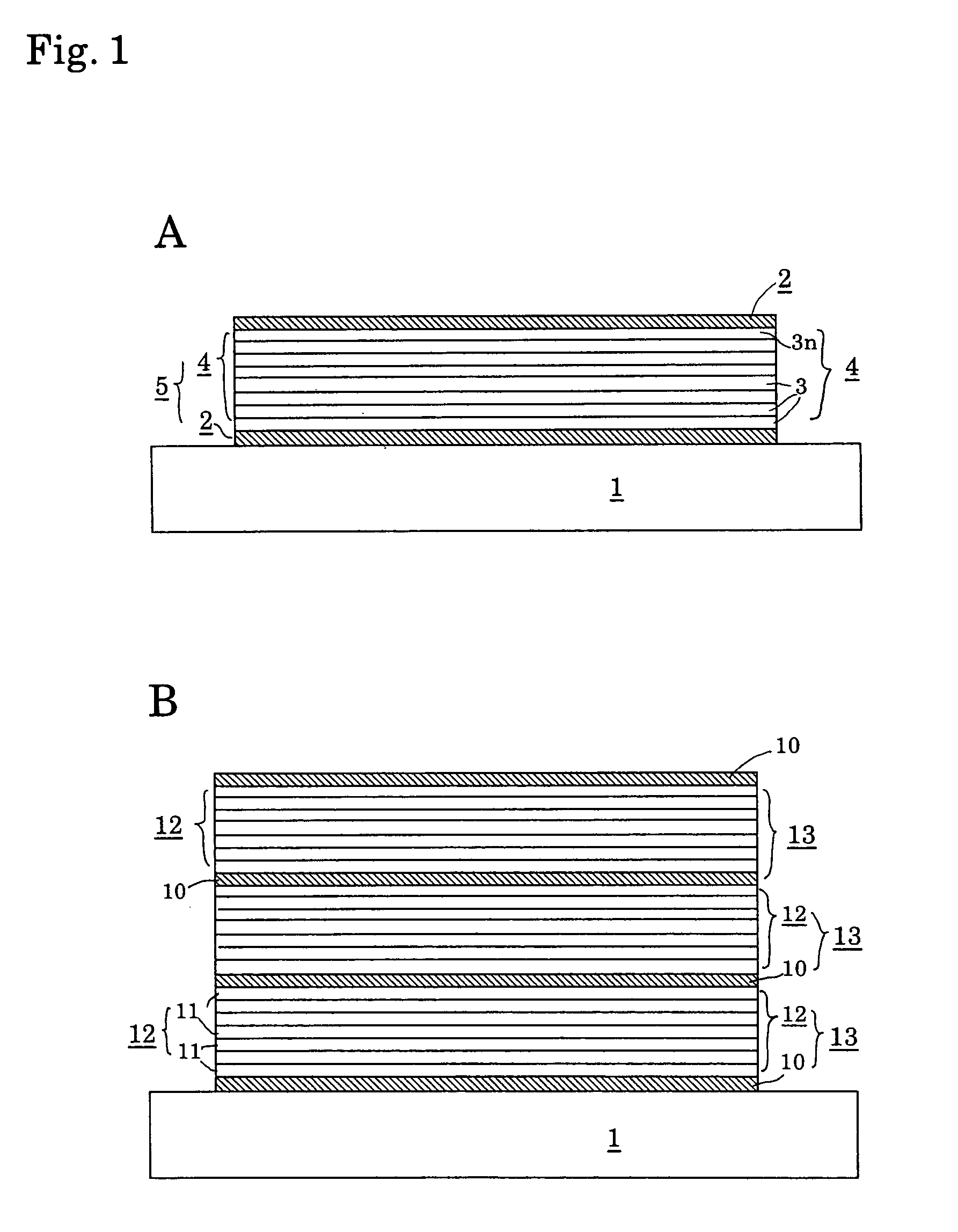
[0040]The Nd and Fe ingot shown in Table 1 was used as the starting material. A 200 mm silicon wafer for commercial integrated circuits (product that corresponded to the standards of the Japan Electronic Industry Development Association (JAIDA)) was used as the single-crystal Si wafer (substrate material), and a sputtering apparatus was used to perform sputtering and to alternately layer monoatomic Nd layers and atomic layered units obtained by layering a plurality of monoatomic Fe layers, yielding thin-film rare-earth permanent magnets in which a monoatomic Nd layer was the uppermost layer.

[0041]Table 2 lists the film thicknesses and number of layers in the resulting thin-film rare-earth permanent magnets. Some of the layered films thus obtained were heat-treated in a vacuum at the temperatures shown in Table 2, and the magnetic characteristics thereof were measured by a vibrating sample magnetometer The results are shown in Table 2.


PUM

PropertyMeasurementUnit
Magnetic fieldaaaaaaaaaa
Lengthaaaaaaaaaa
Auxiliary magnetic fieldaaaaaaaaaa

Abstract

An anisotropic thin-film rare-earth permanent magnet endowed with high magnetic characteristics by rendering a vapor-phase-grown thin film anisotropic in the layering direction. The atomic laminate units are formed by laminating a monoatomic layer of a rare earth element on a substrate of a non-magnetic material having, a flat smoothness and then by laminating an atomic laminate of a transition metal element having a plurality of monoatomic layers of a transition metal element, so that the atomic laminate units of a characteristic construction are laminated in a plurality of layers. As a result, each atomic laminate of the transition metal element has an easy magnetizable axis in the laminate direction of the monoatomic layers and which are sandwiched between a monoatomic layer of a rare-earth element so that an inverse magnetic domain is suppressed to establish a strong coercive force. Moreover, the content of the transition metal element to the rare-earth metal is raised to improve the residual magnetic flux density drastically.

Description

[0001]This is a U.S. national phase application under 35 U.S.C. 371 of International Patent Application No. PCT / JP01 / 06562, filed Jul. 30, 2001, and claims the benefit of Japanese Patent Application No. 2000-233936, filed Aug. 2, 2000. The International Application was published iii Japanese on Feb. 21, 2002 as WO 02 / 15206 A1 under PCT Article 21(2).TECHNICAL FIELD[0002]The present invention relates to a thin-film rare-earth permanent magnet, and more particularly to a thin-film rare-earth permanent magnet whose structure has one or more atomic layered units in which a monoatomic layer of a rare-earth element is formed on a substrate of a nonmagnetic material with excellent surface hardness and flatness, such as a single-crystal silicon wafer, and in which a plurality of monoatomic layers of a transition metal element are then layered to produce a thin-film magnet that has high magnetic characteristics and possesses an axis of easy magnetization in the layering direction; and to a m...

Claims


Application Information

Patent Timeline
IPC IPC(8): B32B7/02B32B15/01B32B15/04C23C14/00C23C14/16H01F10/00H01F10/12H01F10/28H01F10/32H01F41/30
CPCB82Y25/00C23C14/00C23C14/16H01F10/007H01F10/126H01F10/28H01F10/3222H01F10/3227H01F41/302B82Y40/00Y10T428/12931Y10T428/32Y10T428/325Y10T428/12875Y10T428/1129Y10T428/24975Y10T428/115Y10T428/12861Y10T428/12937Y10T428/12868
Inventor YAMASHITA, OSAMUMAKITA, KEN
Owner SUMITOMO SPECIAL METAL CO LTD
Why Eureka
Try Eureka