

Feed forward equalizer and a method for analog equalization of a data signal
a data signal and equalization method technology, applied in pulse manipulation, pulse technique, line-transmission details, etc., can solve the problems of complex equalization of data stream upstream of a data recovery unit, data signal at the receiver being subject to distortion, and degrading received signals, etc., to achieve low technical complexity and easy implementation
- Summary
- Abstract
- Description
- Claims
- Application Information
AI Technical Summary
Benefits of technology
Problems solved by technology
Method used
Image

Examples
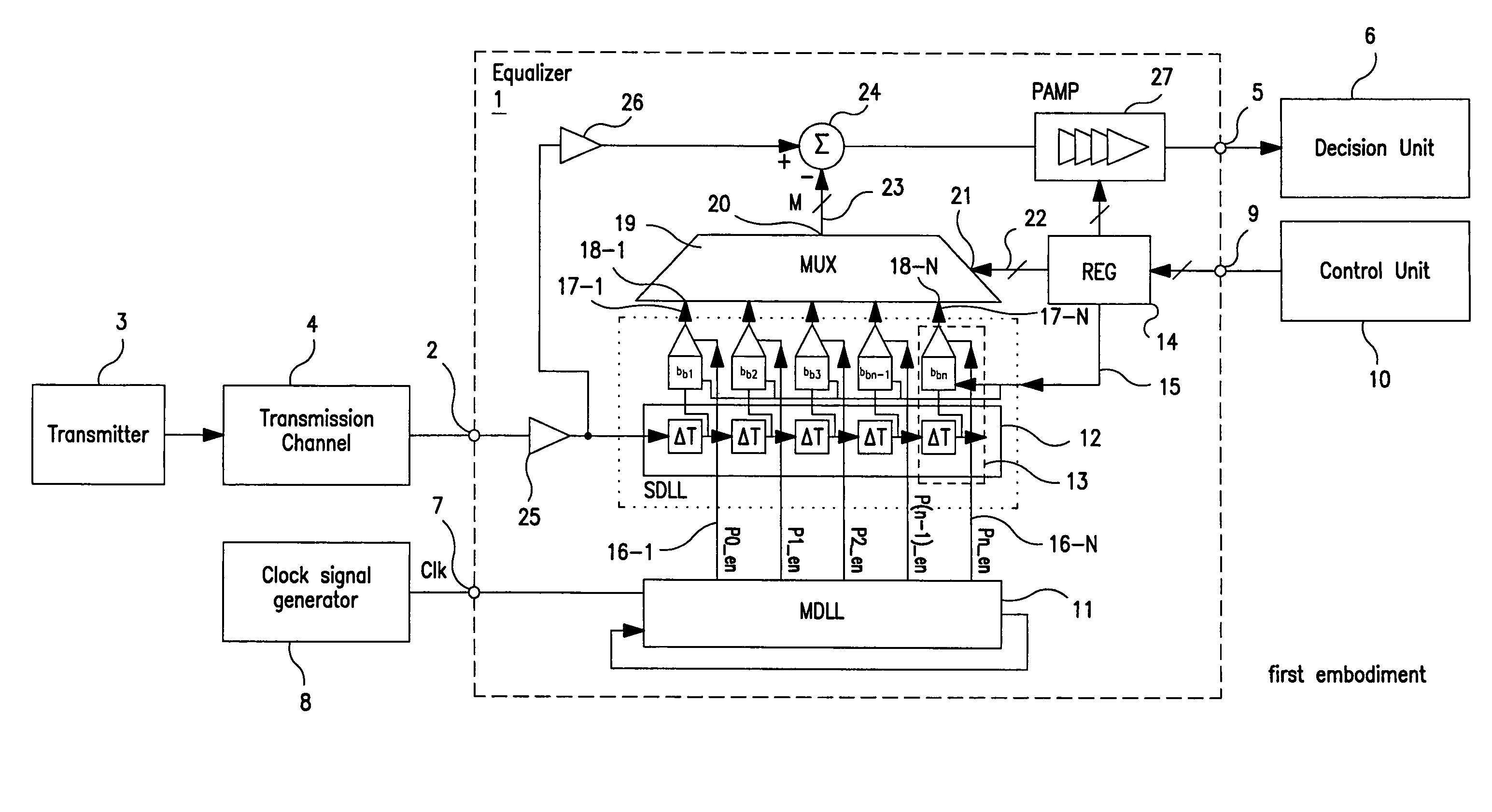
first embodiment
[0081]As can be seen from FIG. 5 which shows the feed forward equalizer 1 according to the present invention the equalizer 1 receives at a data input 2 a high frequency serial data signal transmitted by a transmitter 3 via a data transmission channel 4. The feed forward equalizer 1 according to the present invention is provided to eliminate intersymbol interferences (ISI) caused by the data transmission channel 4. The feed forward equalizer 1 according to the present invention comprises a data output 5 which supplies an equalized output data signal or a decision unit 6 of a receiver. The feed forward equalizer 1 according to the present invention further comprises a clock input terminal 7 for reception of a reference clock signal (CLK). The reference clock signal (CLK) is either generated by a clock signal generator 8 or is formed by a system clock signal. The feed forward equalizer 1 according to the present invention further comprises a control input terminal 9 for reception of a ...
second embodiment
[0109]FIG. 9 shows the feed forward equalizer 1 as shown in FIG. 8 in more detail.
[0110]In the second embodiment as shown in FIG. 9 each slave delay unit 13-i comprises a slave delay element 13a-i, an analog amplifier 13b-i and a coefficient register 13c-i as in the first embodiment shown in FIG. 7. However, in the second embodiment of FIG. 9 each slave delay unit 13-i further comprises a decentralized summation point 24-i and a signal buffer 26-i. The decentral summation points 24-i of the slave delay units 13-i are connected to respective input terminals 18 of the multiplexer 19 which switches the decentral summation points through to an output of the multiplexer depending on a control word stored in the control register 14. The equalized output signal is amplified by the output amplifying stage 27 and supplied to a decision unit of a receiver via an output terminal 5 of the feed forward equalizer 1. The advantage of the second embodiment of the feed forward equalizer 1 as shown ...
PUM
 Abstract
Description
Claims
Application Information