

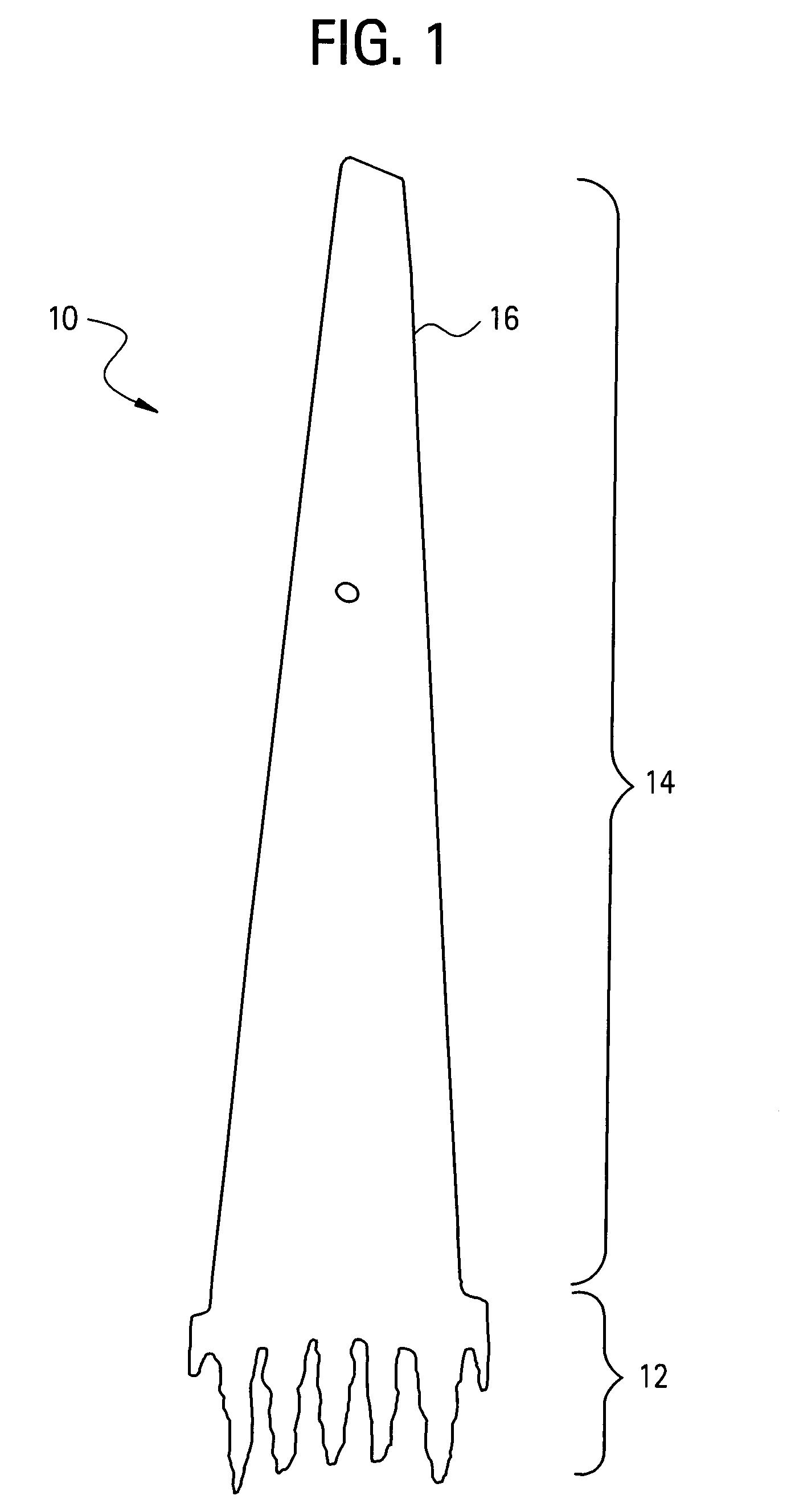
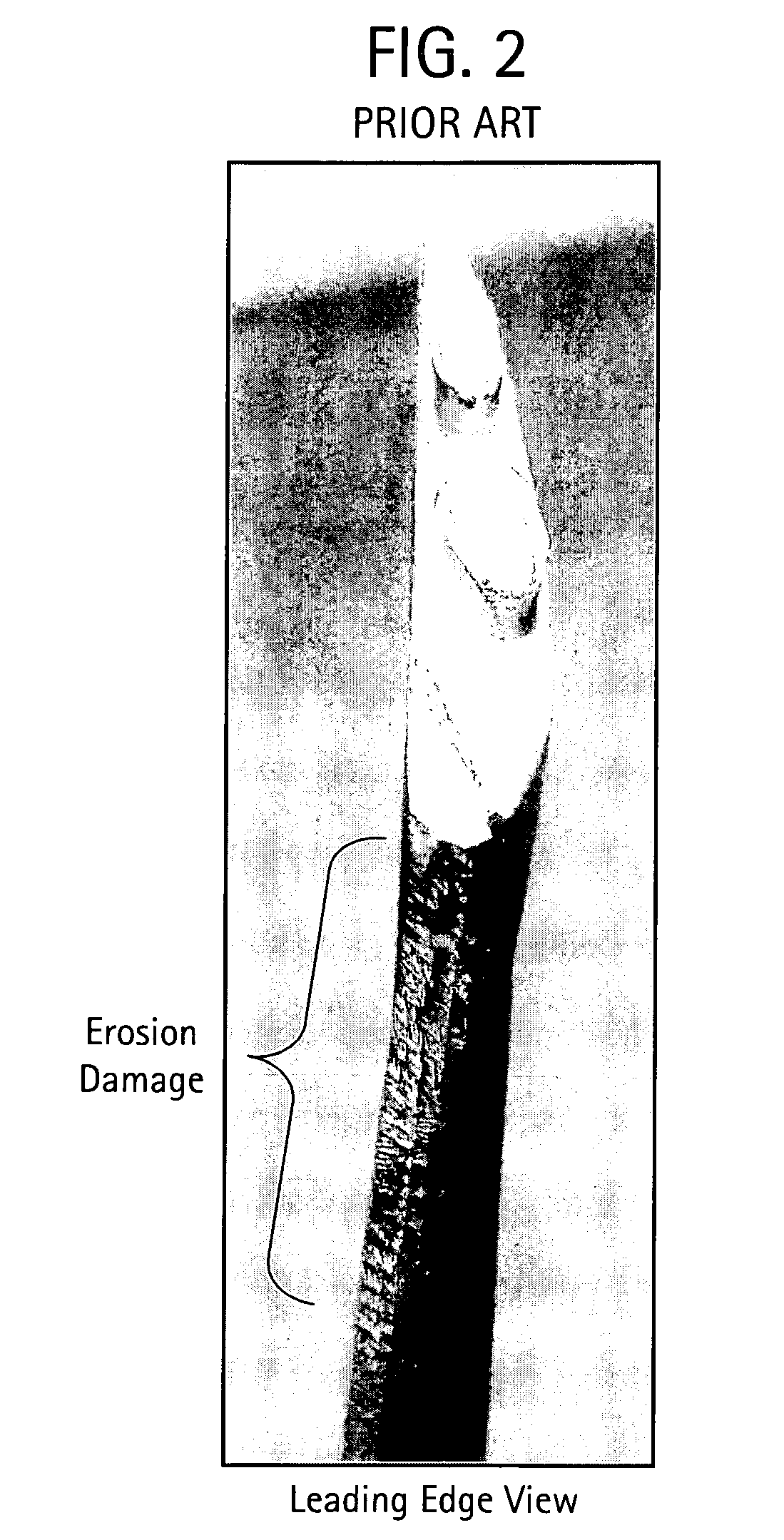
Erosion and wear resistant protective structures for turbine engine components
a protective structure and turbine engine technology, applied in the direction of liquid fuel engine components, non-electric welding apparatus, non-positive displacement fluid engines, etc., can solve the problems of power loss, progressive loss of bucket material, wear coating on turbine engine parts that are susceptible to wear,
- Summary
- Abstract
- Description
- Claims
- Application Information
AI Technical Summary
Benefits of technology
Problems solved by technology
Method used
Image

Examples
example 1
[0047]In this example, a NiTi shape memory alloy (56 wt % Ni, 44 wt % Ti) was joined to a Fe-based alloy using a HIP device at a temperature of 900° C. and a pressure of about 30 ksi. A cross section of the so-formed joint is illustrated in FIG. 4.
example 2
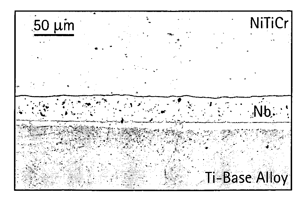
[0048]In this example, the NiTiCr shape memory alloy was joined to the Ti-based alloy with a Nb diffusion-controlling layer sandwiched therebetween. A cross section of the so-formed joint is illustrated in FIG. 5. No cracking is observed by optical and scanning electron microscopy and the joint formed appears to be firmly bonded.
example 3
[0049]In this example, a NiTiFe alloy (52 wt % Ni, 45 wt % Ti, and 3 wt % Fe) a Nb diffusion-controlling layer, and a Ti-based alloy were co-extruded using the extrusion process at a temperature of 900° C. and an area reduction ratio of 4:1. The NiTi based alloy and Ti-based alloy were preheated for 2 hours at a temperature of 900° C. A cross section of the so-formed joint is illustrated in FIG. 6. The interface between the NiTiFe and Ti-based alloy with the Nb diffusion-controlling layer appears uncracked and firmly bonded.
PUM
| Property | Measurement | Unit |
|---|---|---|
| grain size | aaaaa | aaaaa |
| pressure | aaaaa | aaaaa |
| temperature | aaaaa | aaaaa |
Abstract
Description
Claims
Application Information