Method and apparatus for control and routing of wireless sensor networks

a wireless sensor and network control technology, applied in the field of wireless sensor network control and routing schemes, can solve the problems of limited storage, processing, communication, storage and battery at sensor nodes, and difficult practical implementation, and achieve high failure rate of sensor nodes, efficient data packet routing, and reliable data packet delivery

Active Publication Date: 2007-12-04
VIRGINIA TECH INTPROP INC
View PDF9 Cites 87 Cited by
  • Summary
  • Abstract
  • Description
  • Claims
  • Application Information

AI Technical Summary

Benefits of technology

[0018]It is therefore an object of the present invention to provide a method for network control and routing in a wireless sensor network that will perform well as the size of the network grows.

Problems solved by technology

However, the stringent physical constraints involved in designing sensor nodes (i.e., size, cost, and energy) have imposed a severely limited design space on hardware and software complexity, making practical implementation a challenging task.
Specifically, for a future sensor node packaged on a cubic-millimeter scale or even smaller, the storage, processing, and communication capabilities on the node will be extremely limited.
But in reality, when the size of a sensor node goes down to a cubic-millimeter scale, the processing, communication, storage and battery at a sensor node are extremely limited.
Although these protocols have less computational complexity in routing, they have extra hardware requirements and control overhead on acquiring and distributing location information (e.g., using GPS devices or querying a location database).
Therefore, a considerable amount of energy may be spent on maintaining the clusters.
Furthermore, the cluster heads communicate directly to the base stations, which is more energy consuming than multi-hop routing.
In addition, wireless links in a wireless sensor network are fragile and error-prone.

Method used


Image

  • Method and apparatus for control and routing of wireless sensor networks
  • Method and apparatus for control and routing of wireless sensor networks
  • Method and apparatus for control and routing of wireless sensor networks

Examples


Embodiment Construction

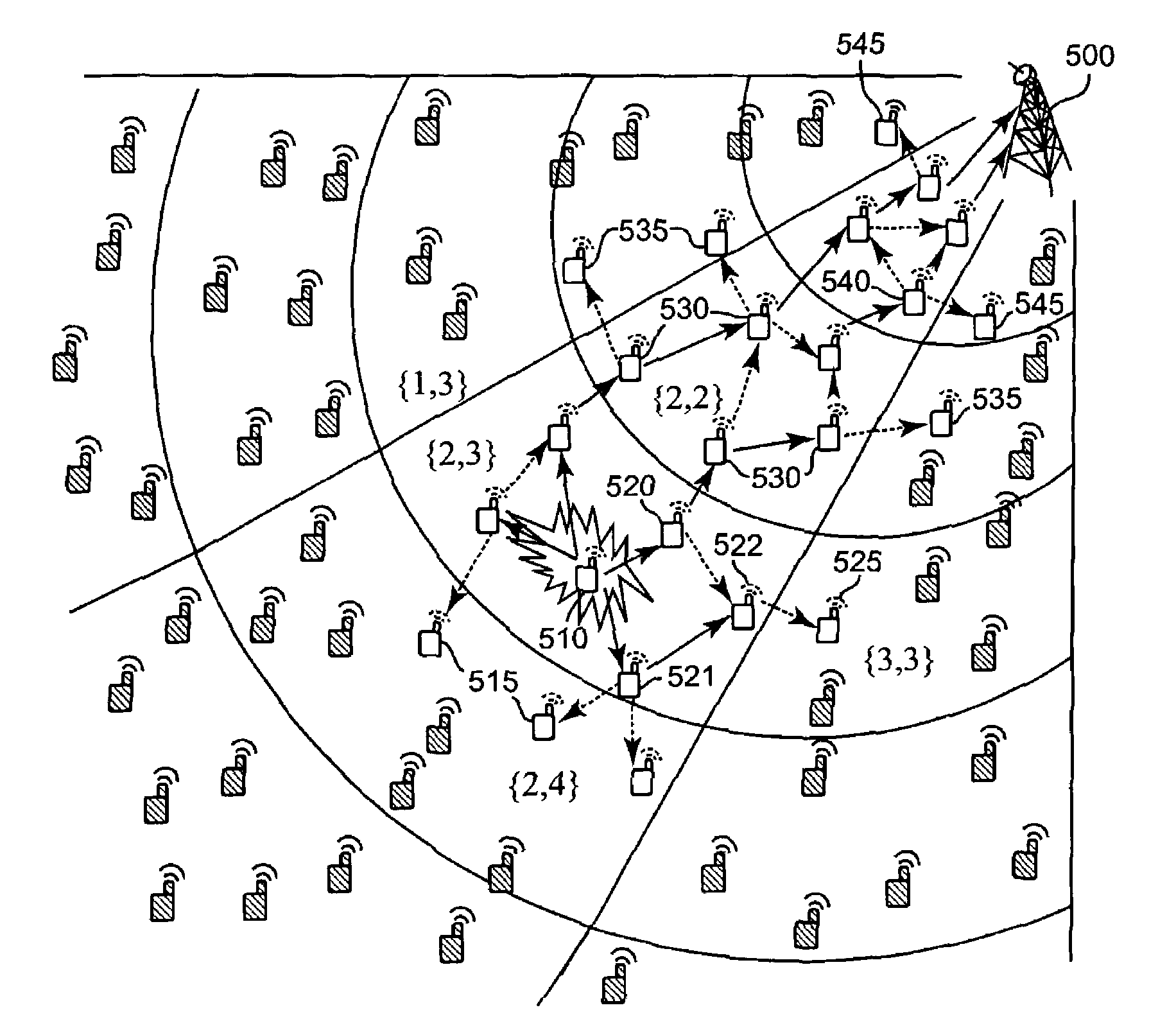
[0044]Consider a large-scale, dense sensor network consisting of thousands or even millions of sensors over a wide region sensing, e.g., chemical and biological agents. Assume that each sensor node is equipped with an inexpensive omni-directional antenna with a short transmission range. Should there be an event (e.g. release of a chemical or biological agent into the sensed field), the sensor data must be quickly-relayed to the base station along the sensor network cloud.

[0045]For such large scale sensor networks, fully-distributed network control and routing algorithms, although technically correct, may result in substantial algorithm complexity to perform control functions (e.g., localization, synchronization, and message exchanges to build up and maintain routing tables), or high requirements on the sensor node design (e.g., CPU, memory, energy, or communication), which may not be suitable to sensor nodes on the order of cubic millimeter or even smaller. Although hierarchical or ...


PUM


Abstract

A scalable, minimum node complexity, energy efficient, and error-resilient routing method for wireless sensor networks is described. The network is partitioned into regions by power controlled base station scans using a directional antenna. Routing is performed using only local location information and instructions received from the base station at each sensor node with minimum processing and control overhead, thus allowing simple, low-cost sensor designs. Sensors in the network provide to a base station reports of the condition of the sensors themselves, and these reports are analyzed by the base station to determine improved routing instructions, which are then provided to the sensor nodes in control messages. Each data packet is relayed in an interleaved, loop-free mesh of sectors toward the base station, making data delivery robust to sensor failures and transmission errors. The disclosure also contains descriptions for simple edge-based tasking, query, code distribution, and network programming for sensor nodes. The method is suitable for large-scale, dense sensor networks for detection, alarming, and monitoring applications.

Description

[0001]This application claims the benefit of Provisional Application No. 60 / 617,661 entitled A Directional Antenna-Enabled Routing Table-Free Data Forwarding Scheme for Wireless Sensor Networks filed on Oct. 13, 2004. The invention was made under partial support of grant number ANI-0312655 from the National Science Foundation.BACKGROUND OF THE INVENTION[0002]1. Field of the Invention[0003]The present invention generally relates to wireless sensor networks, and more particularly to control and routing schemes for such networks.[0004]2. Background Description[0005]In recent years, as the cost of mass produced semiconductor devices has declined, it has become feasible to deploy networks of small devices for sensing fields in the physical world and transmitting sensed data for analysis. These devices can be deployed to provide dense monitoring close to physical phenomena of interest. For example, such sensors can be used to monitor environmental parameters (such as humidity and temperat...

Claims


Application Information

Patent Timeline
Patent Type & Authority Patents(United States)
IPC IPC(8): H04Q7/24H04W40/00H04W40/06H04W84/18
CPCH01Q1/246H01Q25/00H04W52/322H04W28/04H04W40/00H04W40/06H04W48/08Y02B60/50H04W64/00H04W84/18H04W88/04H04W88/08Y02B60/42Y02D30/00Y02D30/70
Inventor MAO, SHIWENHOU, YIWEI T.
Owner VIRGINIA TECH INTPROP INC
Why Eureka
Try Eureka